Test F: Powertrain Control Module (Pcm) Does Not Respond To NGS Tester
- Perform data link diagnostics. See DATA LINK DIAGNOSTICS
under COMMUNICATION NETWORK DIAGNOSTICS. If scan tool displays PCM:NO RESPONSE ON CKT 914 (BUS+) PCM;NO RESPONSE/NOT EQUIPPED, go to next step. If scan tool does not display PCM:NO RESPONSE ON CKT 914 (BUS+) PCM;NO RESPONSE/NOT EQUIPPED, go to step 6).
- Turn ignition off. Disconnect Powertrain Control Module (PCM) connector C174 located on right side of engine compartment. Inspect PCM connector C174 and Data Link Connector (DLC) C228 for physical damage, bent terminals or corrosion. Repair as necessary and retest system. If connectors are okay, go to next step.
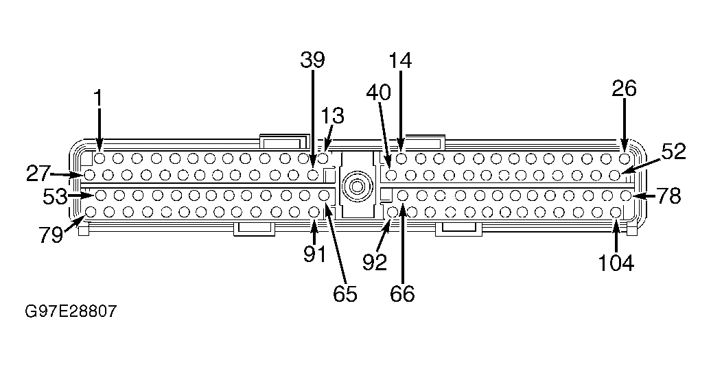
- Measure resistance of Tan/Orange wire between PCM connector C174, terminal No. 16 and DLC C228, terminal No. 2. See Figure
and Fig 1
. If resistance is less than 5 ohms, go to step 6). If resistance is 5 ohms or more, go to next step.
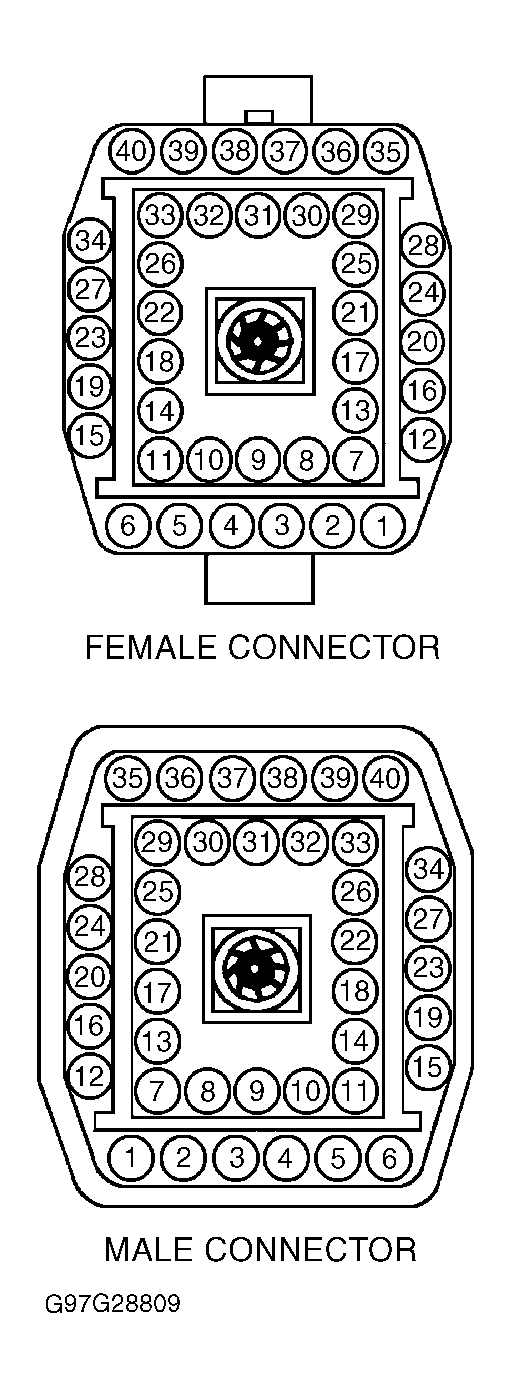
- Disconnect and inspect both halves of bulkhead connector C158 located at left rear of engine compartment. See Fig 2
. Inspect connectors for physical damage, bent terminals or corrosion. Repair as necessary and retest system. If connectors are okay, go to next step.
- Measure resistance of Tan/Orange wire between PCM connector C174, terminal No. 16 and male half of bulkhead connector C158, terminal No. 25. See Fig 1
and Fig 2
. If resistance is less than 5 ohms, repair connectors and/or replace circuits No. 914 (Tan/Orange wire) and No. 915 (Pink/Light Blue wire) between female half of bulkhead connector C158 and DLC C228. Retest system. If resistance is 5 ohms or more, repair connectors and/or replace circuits No. 914 (Tan/Orange wire) and No. 915 (Pink/Light Blue between male half of bulkhead connector C158 and PCM connector C174. Retest system.
- Disconnect Powertrain Control Module (PCM) connector C174 located on right side of engine compartment. Inspect PCM connector C174 and Data Link Connector (DLC) C228 for physical damage, bent terminals or corrosion. Repair as necessary and retest system. If connectors are okay, go to next step.
- Measure resistance of Pink/Light Blue wire between PCM connector C174, terminal No. 15 and DLC C228, terminal No. 10. See Figure
and Fig 1
. If resistance is 5 ohms or more, go to next step. If resistance is less than 5 ohms, perform QUICK TEST. See TESTS W/CODES
article in ENGINE PERFORMANCE section.
- Disconnect and inspect both halves of bulkhead connector C158 located at left rear of engine compartment. See Fig 2
. Inspect connectors for physical damage, bent terminals or corrosion. Repair as necessary and retest system. If connectors are okay, go to next step.
- Measure resistance of Pink/light Blue wire between PCM connector C174, terminal No. 15 and male half of bulkhead connector C158, terminal No. 29. See Fig 1
and Fig 2
. If resistance is less than 5 ohms, repair connectors and/or replace circuits No. 914 (Tan/Orange wire) and No. 915 (Pink/Light Blue wire) between female half of bulkhead connector C158 and DLC C228. Retest system. If resistance is 5 ohms or more, repair connectors and/or replace circuits No. 914 (Tan/Orange wire) and No. 915 (Pink/Light Blue wire between male half of bulkhead connector C158 and PCM connector C174. Retest system.
 Courtesy of FORD MOTOR CO.
 Courtesy of FORD MOTOR CO.