Data Link Diagnostic Test
- Connect New Generation Star (NGS) tester to Data Link Connector (DLC), if not already connected. Turn ignition on. If NGS tester powers up, go to next step. If NGS tester does not power up, go to step 6
.
- Rotate dial on NGS tester to menu item DATA LINK DIAGNOSTICS and press trigger. A test will be performed on the bus for module communications network and the ISO 9141 communication link. If NGS tester displays CKT 914 = SYSTEM PASSED and CKT 915 = SYSTEM PASSED, module communications network is okay. If NGS tester displays CKT 70 = SYSTEM PASSED, ISO 9141 communication link is operating properly. Return to article that directed you here and continue diagnosis. If NGS tester does not display SYSTEM PASSED, go to next step.
- If NGS tester displays ABS: NO RESPONSE/NOT EQUIPPED, see TEST A: ANTI-LOCK BRAKE SYSTEM CONTROL MODULE DOES NOT RESPOND TO SCAN TOOL
. If scan tool displays AIR BAG: NO RESPONSE/NOT EQUIPPED, see TEST B: AIR BAG CONTROL MODULE DOES NOT RESPOND TO SCAN TOOL
. If result code for CKT 70 = 00000001, see TEST C: AIR BAG CONTROL MODULE & ANTI-LOCK BRAKE SYSTEM CONTROL MODULE DO NOT RESPOND TO SCAN TOOL - RESULT CODE 70 = 00000001
. If NGS tester display is other than specified, go to next step.
- If NGS tester displays PCM: NO RESPONSE/NOT EQUIPPED, see TEST D: POWERTRAIN CONTROL MODULE DOES NOT RESPOND TO SCAN TOOL
. If NGS tester display is other than specified, go to next step.
- If result code for CKT 914 or CKT 915 is 00000003 and all modules respond with NO RESPONSE ON CKT 914 (BUS +) or NO RESPONSE ON CKT 915 (BUS -), see TEST F: NO MODULE/NETWORK COMMUNICATION - RESULT CODE 00000003
. If NGS tester response was not as specified, see SYMPTOM INDEX
table under SYSTEM TESTS.
- Check fuse No. 24 (15-amp) located in central junction box. If fuse is okay, go to next step. If fuse is open, replace fuse and check system for normal operation. If fuse fails, check related circuits for short to ground. Repair as necessary.
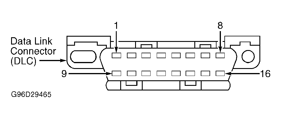
- Disconnect NGS tester. Turn ignition on. Measure voltage between ground and terminal No. 16 (Orange wire) at DLC. See Fig 2
. If voltage is greater than 10 volts, go to step 9
. If voltage is not greater than 10 volts, go to next step.
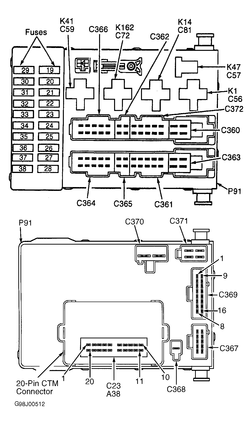
- Turn ignition off. Disconnect central junction box connector C369. See Fig 1
. Turn ignition on. Measure voltage between ground and terminal No. 1 (Orange wire) at central junction box connector C369 (component side). If voltage is greater than 10 volts, repair open or short to ground in Orange wire or Orange/Yellow wire. If voltage is not greater than 10 volts, replace central junction block.
- Measure resistance between ground and terminal No. 5 (Black/Orange wire) at DLC. See Fig 2
. If resistance is less than 5 ohms, repair open in ground circuit (Black wire) to DLC. If resistance is greater than 5 ohms, repair open in ground circuit (Black/Orange wire) to DLC.
 Courtesy of FORD MOTOR CO.
 Courtesy of FORD MOTOR CO.