Test B: No Communication With Lighting Control Module
- Turn ignition switch to RUN position. Using NGS tester, monitor Lighting Control Module (LCM) PID IGN_LC. If NGS tester does not indicate UNABLE TO PERFORM TEST FUNCTION, MODULE NOT RESPONDING, CHECK IGNITION STATUS/VERIFY CABLE REQUIREMENTS, OR CHECK CABLE CONNECTIONS, go to next step. If NGS tester indicates UNABLE TO PERFORM TEST FUNCTION, MODULE NOT RESPONDING, CHECK IGNITION STATUS/VERIFY CABLE REQUIREMENTS, OR CHECK CABLE CONNECTIONS, go to step 11
.
- Turn ignition switch to RUN position. Using NGS tester, monitor LCM PID IGN_LC while rotating ignition switch through ACCY, OFF and RUN positions. If PID indicates START while ignition switch is in RUN position, go to next step. If PID indicates RUN while ignition switch is in RUN position, go to step 12
. If PID indicates ACCY while ignition switch is in RUN position, go to step 7
.
- Turn ignition switch to LOCK position. Remove fuse No. 6 (15-amp) from instrument panel fuse box. Check fuse. If fuse is okay, go to next step. If fuse is blown, go to step 6
.
- Turn ignition switch to RUN position. Measure voltage at input side of fuse No. 6 in instrument panel fuse box. If battery voltage exists, go to next step. If battery voltage does not exist, repair power supply to fuse No. 6. See appropriate wiring diagram in POWER DISTRIBUTION article in WIRING DIAGRAMS.
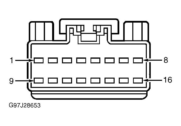
- Turn ignition switch to LOCK position. Install fuse No. 6. Disconnect LCM harness connector C2027. Turn ignition switch to RUN position. Measure voltage at terminal No. 1 (White/Violet wire) at LCM harness connector C2027. See Fig 1
. If battery voltage exists, replace LCM. If battery voltage does not exist, repair open in White/Violet wire.
- Turn ignition switch to LOCK position. Disconnect Lighting Control Module (LCM) harness connector C2027. Measure resistance between ground and terminal No. 1 (White/Violet wire) at LCM harness connector C2027. See Fig 1
. If resistance is greater than 10 k/ohms, replace LCM. If resistance is 10 k/ohms or less, repair short to ground in White/Violet wire.
- Turn ignition switch to LOCK position. Remove fuse No. 13 (15-amp) from instrument panel fuse box. Check fuse. If fuse is okay, go to next step. If fuse is blown, go to step 10
.
- Turn ignition switch to RUN position. Measure voltage at input side of fuse No. 13 in instrument panel fuse box. If battery voltage exists, go to next step. If battery voltage does not exist, repair power supply to fuse No. 13. See appropriate wiring diagram in POWER DISTRIBUTION article in WIRING DIAGRAMS.
- Turn ignition switch to LOCK position. Install fuse No. 13 (15-amp). Disconnect LCM harness connector C2027. Turn ignition switch to RUN position. Measure voltage at terminal No. 9 (Red/Yellow wire) at LCM 16-pin connector C2027. See Fig 1
. If battery voltage exists, replace LCM. If battery voltage does not exist, repair open in Red/Yellow wire.
- Turn ignition switch to LOCK position. Disconnect LCM harness connector C2027. Measure resistance between ground and terminal No. 9 (Red/Yellow wire) at LCM harness connector C2027. See Fig 1
. If resistance is greater than 10 k/ohms, replace LCM. If resistance is 10 k/ohms or less, repair short to ground in Red/Yellow wire.
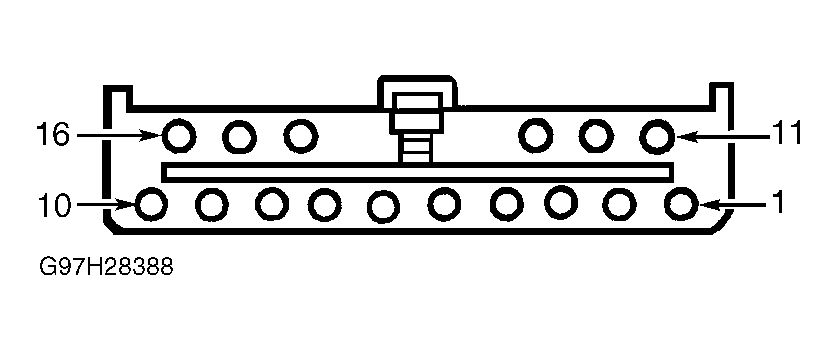
- Turn ignition switch to LOCK position. Disconnect LCM harness connector C2029. Measure resistance between ground and terminals No. 4 and 9 (both Black wire) at LCM harness connector C2029. See Fig 2
. If either resistance reading is greater than 5 ohms, repair open in appropriate Black wire(s). If both resistance readings are 5 ohms or less, repair module communication concern. See MODULE COMMUNICATIONS NETWORK - CROWN VICTORIA & GRAND MARQUIS article.
- Turn ignition switch to LOCK position. Disconnect LCM harness connector C2029. Measure voltage at terminal No. 6 (Tan/White wire) at LCM harness connector C2029. See Fig 2
. If battery voltage does not exist, go to next step. If battery voltage exists, go to step 16
.
- Remove fuse No. 4 (15-amp) from instrument panel fuse box. Measure resistance between ground and terminal No. 6 (Tan/White wire) at LCM harness connector C2029. If resistance is greater than 10 k/ohms, go to next step. If resistance is 10 k/ohms or less, repair short to ground in Tan/White wire and replace fuse.
- Measure voltage at input side of fuse No. 4 in instrument panel fuse box. If battery voltage exists, go to next step. If battery voltage does not exist, repair power distribution circuit. See appropriate wiring diagram in POWER DISTRIBUTION article in WIRING DIAGRAMS.
- Measure resistance in Tan/White wire between output side of fuse No. 4 and terminal No. 6 at LCM harness connector C2029. If resistance is 5 ohms or less, system is okay at this time. If resistance is greater than 5 ohms, repair open in Tan/White wire.
- Measure voltage at terminal No. 11 (Light Green/Yellow wire) at LCM harness connector C2029. If battery voltage does not exist, go to next step. If battery voltage exists, go to step 20
.
- Remove fuse No. 8 (15-amp) from instrument panel fuse box. Measure resistance between ground and terminal No. 11 (Light Green/Yellow wire) at LCM harness connector C2029. If resistance is greater than 10 k/ohms, go to next step. If resistance is 10 k/ohms or less, repair short to ground in Light Green/Yellow wire and replace fuse.
- Measure voltage at input side of fuse No. 8. If battery voltage exists, go to next step. If battery voltage does not exist, repair power distribution circuit. See appropriate wiring diagram in POWER DISTRIBUTION article in WIRING DIAGRAMS.
- Measure resistance in Light Green/Yellow wire between output side of fuse No. 8 and terminal No. 11 at LCM harness connector C2029. If resistance is 5 ohms or less, system is okay at this time. If resistance is greater than 5 ohms, repair open in Light Green/Yellow wire.
- Measure resistance between ground and terminal No. 9 (Black wire) at LCM harness connector C2029. If resistance is 5 ohms or less, repair communication concern. See MODULE COMMUNICATIONS NETWORK - CROWN VICTORIA & GRAND MARQUIS article. If resistance is greater than 5 ohms, repair open in Black wire.
 Courtesy of FORD MOTOR CO.
 Courtesy of FORD MOTOR CO.