Test I: No Module/Network Communication - SCP Network
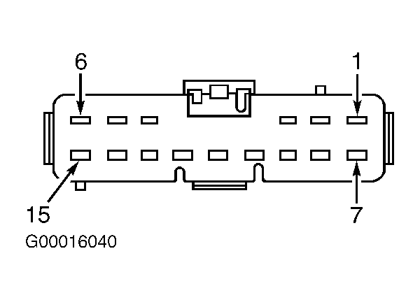
- Turn ignition switch to LOCK position. Disconnect connector C63 from connector C61. See Figure
. Measure resistance of Gray/Red wire between Data Link Connector (DLC) terminal No. 2 and connector C63 terminal No. 15. Measure resistance of Blue/Red wire between DLC terminal No. 10 and connector C63 terminal No. 6. See Figure
and Fig 1
. If resistance is less than 5 ohms in both circuits, go to next step. If resistance is 5 ohms or more in either circuit, repair appropriate circuit and repeat data link diagnostic test. See DATA LINK DIAGNOSTIC TEST
under SELF-DIAGNOSTIC SYSTEM.
- Reconnect connector C63. Measure resistance between ground and DLC terminals No. 2 (Gray/Red wire) and No. 10 (Blue/Red wire). If resistance is more than 10 k/ohms on both circuits, go to step 6
. If resistance is 10 k/ohms or less on one or both circuits, go to next step.
- Disconnect PCM harness connector C415 (except Zetec engine) or C416 (Zetec engine). Measure resistance between ground and DLC terminals No. 2 (Gray/Red wire) and No. 10 (Blue/Red wire). If resistance is more than 10 k/ohms on both circuits, go to step 9
. If resistance is 10 k/ohms or less on one or both circuits, go to next step.
- Disconnect instrument cluster harness connector C809. Measure resistance between ground and DLC terminals No. 2 (Gray/Red wire) and No. 10 (Blue/Red wire). See Figure
. If resistance is more than 10 k/ohms on both circuits, go to next step. If resistance is 10 k/ohms or less on one or both circuits, go to step 10
.
- Repair appropriate circuit between connector C61 and instrument cluster or PCM. See WIRING DIAGRAMS
. Retest system.
- Turn ignition switch to RUN position. Measure voltage between DLC terminal No. 16 (Red wire) and No. 2 (Gray/Red wire). Measure voltage between DLC terminal No. 16 (Red wire) and No. 10 (Blue/Red wire). See Figure
. If voltage is less than 5 volts on one of the checks, go to next step. If voltage is 5 volts or more on one of the checks, SCP network is okay. Check scan tool. Refer to scan tool manufacturer's instructions.
- Turn ignition switch to LOCK position. Disconnect PCM harness connector C415 (except Zetec engine) or C416 (Zetec engine). Turn ignition switch to RUN position. Measure voltage between DLC terminal No. 16 (Red wire) and No. 2 (Gray/Red wire). Measure voltage between DLC terminal No. 16 (Red wire) and No. 10 (Blue/Red wire). See Figure
. If voltage is less than 5 volts on one of the checks, go to next step. If voltage is 5 volts or more on one of the checks, go to step 9
.
- Turn ignition switch to LOCK position. Disconnect instrument cluster harness connector C809. Turn ignition switch to RUN position. Measure voltage between DLC terminal No. 16 (Red wire) and No. 2 (Gray/Red wire). Measure voltage between DLC terminal No. 16 (Red wire) and No. 10 (Blue/Red wire). See Figure
. If voltage is less than 5 volts on one of the checks, repair appropriate circuit and repeat data link diagnostic test. See DATA LINK DIAGNOSTIC TEST
under SELF-DIAGNOSTIC SYSTEM. If voltage is 5 volts or more on one of the checks, go to step 10
.
- Inspect PCM harness connector for loose, damaged or corroded terminals. Repair as necessary. Reconnect all harness connectors and retest system. If symptom still exists, replace PCM and repeat data link diagnostic test. See DATA LINK DIAGNOSTIC TEST
under SELF-DIAGNOSTIC SYSTEM. If symptom does not exist, system is okay at this time.
- Inspect instrument cluster harness connector for loose, damaged or corroded terminals. Repair as necessary. Reconnect all harness connectors and retest system. If symptom still exists, replace instrument cluster and repeat data link diagnostic test. See DATA LINK DIAGNOSTIC TEST
under SELF-DIAGNOSTIC SYSTEM. If symptom does not exist, system is okay at this time.
 Courtesy of FORD MOTOR CO.