Test G: Illuminated Entry Inoperative Using Remote Transmitter
- Turn ignition switch to LOCK position. Connect New Generation Star (NGS) tester following manufacturer's instructions. Using NGS tester, select GEM/CTM PID IGN_GEM. On vehicles with manual transmission, depress clutch while turning ignition switch to START position. On all vehicles, turn ignition switch through all positions. If PID values agree with switch positions, go to next step. If PID values do not agree with switch positions, repair appropriate interior lighting circuit. See
ILLUMINATION/INTERIOR LIGHTS article. Clear DTCs. Recheck system operation.
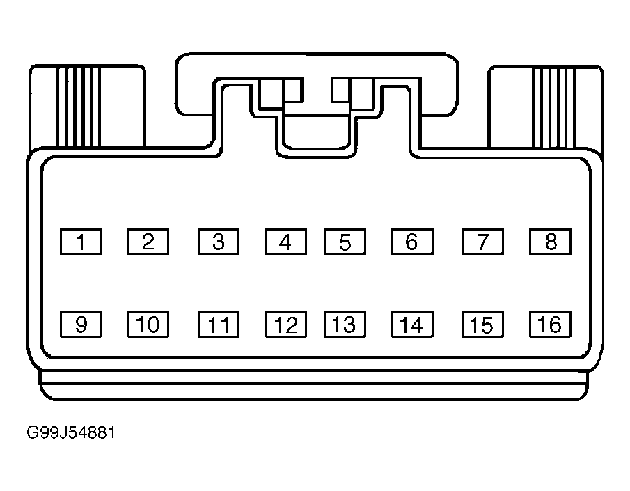
- Turn ignition switch to LOCK position. Connect NGS tester to power supply only. DO NOT connect NGS tester to DLC. Disconnect GEM/CTM 16-pin harness connector C281. Measure voltage between ground and GEM/CTM harness connector C281 terminal No. 9 (Brown/Light Green wire) while pressing UNLOCK button on remote transmitter. See Fig 1. If MIN voltage is less than 1.3 volts when pulse was transmitted, leave meter connected and go to next step. If MIN voltage is more than 1.3 volts when pulse was transmitted, clear MIN voltage and repeat this step to confirm high voltage. If high voltage still exists, replace RAP module. See REMOTE ANTI-THEFT PERSONALITY MODULE under REMOVAL & INSTALLATION. Recheck system operation.
- With meter still connected from previous step, measure illuminated entry pulse widths while pressing UNLOCK button on remote transmitter. If pulse widths are 190-210 milliseconds, go to next step. If pulse widths are not 190-210 milliseconds, replace RAP module. See REMOTE ANTI-THEFT PERSONALITY MODULE under REMOVAL & INSTALLATION. Recheck system operation.
- Disconnect RAP module Gray 22-pin harness connector C338. Measure resistance of Brown/Light Green wire between GEM/CTM harness connector C281 terminal No. 9 and RAP module harness connector C338 terminal No. 10. Measure resistance between ground and GEM/CTM harness connector C281 terminal No. 9 (Brown/Light Green wire). See Figure and Fig 1
. Resistance should be less than 5 ohms between GEM/CTM and RAP module, and more than 10 k/ohms between ground and GEM/CTM. See GENERIC ELECTRONIC MODULE/CENTRAL TIMER MODULE under REMOVAL & INSTALLATION. If resistance is as specified, replace GEM/CTM. Clear DTCs and recheck system operation. If resistance is not as specified, repair open or short to ground in Brown/Light Green wire. Recheck system operation.
 Courtesy of FORD MOTOR CO.