Test A: Warning Indicator On With Engine Running
- Test battery condition. If battery is okay, go to next step. If battery is defective, replace battery.
- Remove and inspect battery junction box fuse No. 10 (10-amp). If fuse is okay, go to next step. If fuse is not okay, replace fuse. If fuse blows again, repair short to ground in Red wire.
- Perform GENERATOR LOAD TEST under ON-VEHICLE TESTING. If generator output is okay, diagnose charging system warning indicator. See appropriate ANALOG INSTRUMENT PANELS article in ACCESSORIES & EQUIPMENT. If generator output is not okay, go to next step.
- Turn ignition on. Measure voltage between negative battery terminal and generator housing. If voltage is less than .5 volt, go to next step. If voltage is greater than .5 volt, clean and tighten generator mounting and negative battery cable connection. If fault is still present, replace negative battery cable.
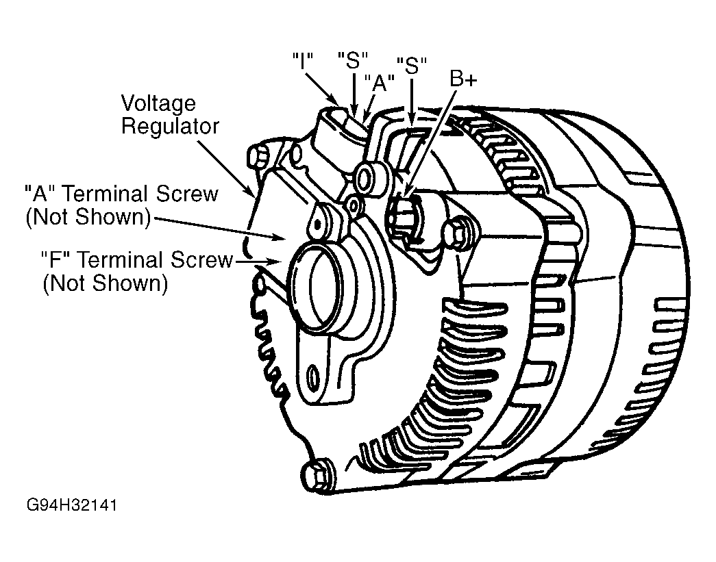
- Measure voltage between generator terminal B+ and positive battery terminal. See Fig 1. If voltage is less than .5 volt, go to next step. If voltage is greater than .5 volt, clean and tighten positive battery cable connection. Retest system operation. If fault is still present, replace positive battery cable.
- Measure voltage of Red wire at generator terminal B+. See Fig 1. If battery voltage is present, go to next step. If battery voltage is not present, repair Red wire between generator and battery junction box. See WIRING DIAGRAMS . Retest system operation.
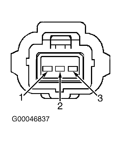
- Turn ignition off. Disconnect generator 3-pin connector. Measure voltage at generator 3-pin harness connector terminal No. 3 (Red wire). See Fig 2. If voltage is greater than 10 volts, go to next step. If voltage is less than 10 volts, inspect battery junction box fuse No. 10 (10-amp). If fuse is blown, replace fuse and retest system operation. If fuse is okay, repair open in Red wire between generator and battery junction box. See WIRING DIAGRAMS . Retest system operation.
- Reconnect generator 3-pin harness connector. Connect NGS tester to DLC. Turn ignition on. Using NGS tester, retrieve and record PCM DTCs. If any DTCs are retrieved, see appropriate SELF-DIAGNOSTICS article in ENGINE PERFORMANCE. If no DTCs are retrieved, replace generator. See GENERATOR under REMOVAL & INSTALLATION. Retest system operation.
 Courtesy of FORD MOTOR CO.
 Courtesy of FORD MOTOR CO.