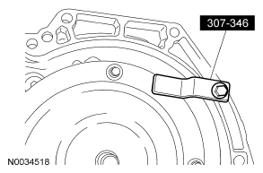
- Make sure that the torque converter is installed correctly.
CAUTION:
Lubricate the torque converter pilot hub with multi-purpose grease.
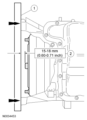
- Check the installation depth of the torque converter.
- Lay a steel straightedge on the automatic transaxle flange.
- Check the installation depth between the transaxle flange and the torque converter centering spigot for the correct clearance.
 Courtesy of FORD MOTOR CO.
- Remove the special tool.
 Courtesy of FORD MOTOR CO.
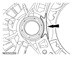
- If the transaxle was replaced, install the transaxle opening cover.
 Courtesy of FORD MOTOR CO.
- Using a high-lift jack, secure the transaxle using a safety strap.
NOTE:
Make sure that the dowel pins are installed in the engine block prior to installing the transaxle.
- Move the transaxle into position.
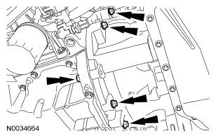
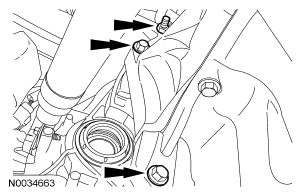
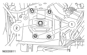
- Note the location of the different length bolts and install the 5 converter housing bolts.
- Tighten to 47 Nm (35 lb-ft).
 Courtesy of FORD MOTOR CO.
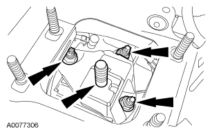
- Install the 3 converter housing bolts.
- Tighten to 47 Nm (35 lb-ft).
 Courtesy of FORD MOTOR CO.
CAUTION:
Only rotate the engine in a clockwise direction or engine damage will occur.
NOTE:
Only install new self-locking nuts.
- Install 4 new torque converter-to-flexplate nuts.
- Tighten to 40 Nm (30 lb-ft).
 Courtesy of FORD MOTOR CO.
- Remove the safety strap from the transaxle.
NOTE:
Inspect the O-ring for damage before installing the fluid filler tube.
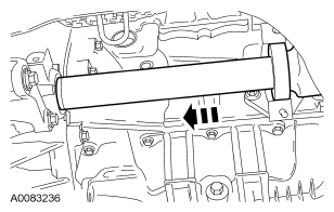
- Install the fluid filler tube.
- Tighten to 8 Nm (71 lb-in).
 Courtesy of FORD MOTOR CO.
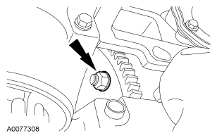
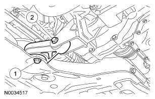
- Install the engine rear mount bracket.
- Tighten to 80 Nm (59 lb-ft).
 Courtesy of FORD MOTOR CO.
NOTE:
Using the engine support bar, raise the engine and transaxle assembly slightly to install rear mount.
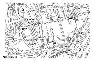
- Install the engine rear mount and nuts.
- Tighten to 48 Nm (35 lb-ft).
- Tighten to 150 Nm (111 lb-ft).
 Courtesy of FORD MOTOR CO.
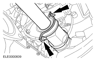
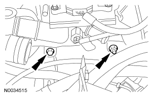
- Install the fluid cooler tubes.
 Courtesy of FORD MOTOR CO.
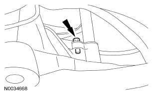
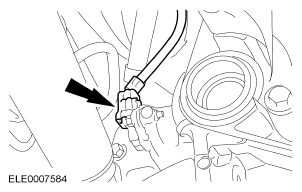
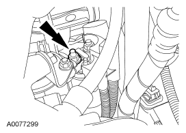
- Connect the output shaft speed (OSS) sensor electrical connector.
 Courtesy of FORD MOTOR CO.
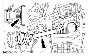
NOTE:
Install a new snap ring.
- Install the LH drive halfshaft.
 Courtesy of FORD MOTOR CO.
NOTE:
Install new nuts and a new center bearing cap.
- Install the RH halfshaft together with the intermediate shaft.
 Courtesy of FORD MOTOR CO.
- Install the mounting bracket for the halfshaft intermediate bearing.
- Tighten to 25 Nm (18 lb-ft).
 Courtesy of FORD MOTOR CO.
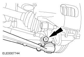
- Install both of the lower control arms to the knuckles.
- Tighten to 63 Nm (46 lb-ft).
 Courtesy of FORD MOTOR CO.
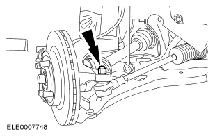
- Install both of the tie-rod ends to the knuckles.
- Tighten to 40 Nm (30 lb-ft).
 Courtesy of FORD MOTOR CO.
- Connect the stabilizer bar at the strut.
- Tighten to 55 Nm (41 lb-ft).
 Courtesy of FORD MOTOR CO.
- Install the front wheels and tires. For additional information, refer to WHEELS AND TIRES
.
- Install the engine RH support insulator.
- Install the insulator bolt and nut.
- Tighten to 48 Nm (35 lb-ft).
- Install the bolt.
- Tighten to 48 Nm (35 lb-ft).
 Courtesy of FORD MOTOR CO.
- Install the starter isolator.
 Courtesy of FORD MOTOR CO.
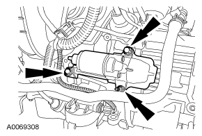
- Install the starter motor and insert the 3 bolts.
- Tighten to 35 Nm (26 lb-ft).
 Courtesy of FORD MOTOR CO.
- Connect the oil sending unit.
- Connect the starter motor electrical connectors.
 Courtesy of FORD MOTOR CO.
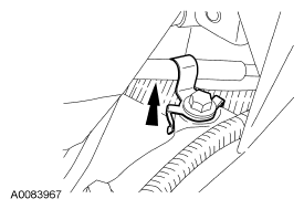
- Connect the bracket to the starter stud.
 Courtesy of FORD MOTOR CO.
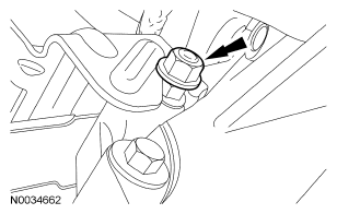
- Install the fluid filler tube and shift cable bracket bolts.
- Tighten to 20 Nm (15 lb-ft).
- Tighten to 8 Nm (71 lb-in).
 Courtesy of FORD MOTOR CO.
- Note the location of the different length bolts and install the upper center converter housing bolts.
- Tighten to 47 Nm (35 lb-ft).
 Courtesy of FORD MOTOR CO.
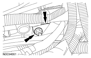
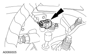
- Position the electrical connector bracket and install the nut.
- Tighten to 25 Nm (18 lb-ft).
 Courtesy of FORD MOTOR CO.
- Install the electrical connector bracket nut.
- Tighten to 25 Nm (18 lb-ft).
 Courtesy of FORD MOTOR CO.
- Install the shift cable clip.
- Tighten to 47 Nm (35 lb-ft).
 Courtesy of FORD MOTOR CO.
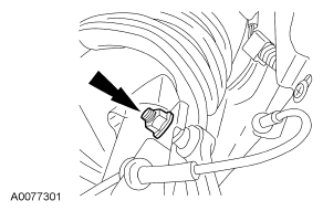
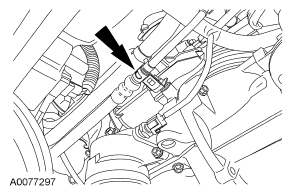
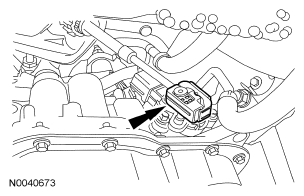
- Connect the turbine shaft speed (TSS) sensor electrical connector.
 Courtesy of FORD MOTOR CO.
- Connect the shift cable to the manual control lever.
 Courtesy of FORD MOTOR CO.
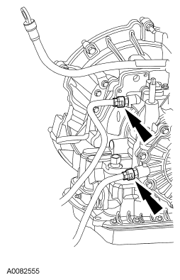
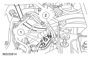
NOTE:
The TR connector seal is a high compression type and requires a "press to click" installation for a weatherproof seal.
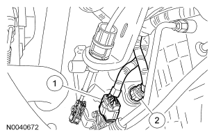
- Connect the electrical connectors.
- Transmission range (TR) sensor.
- Transaxle solenoid electrical connector.
 Courtesy of FORD MOTOR CO.
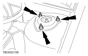
- Tighten the LH strut and spring assembly top mount nuts.
- Tighten to 30 Nm (22 lb-ft).
 Courtesy of FORD MOTOR CO.
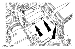
- Install the air cleaner resonator.
- Install the resonator and nuts.
- Connect the air cleaner outlet hose.
- Connect the crankcase ventilation hose.
 Courtesy of FORD MOTOR CO.
NOTE:
When the battery has been disconnected and reconnected, some abnormal drive symptoms may occur while the vehicle relearns its adaptive strategy. The vehicle may need to be driven to relearn the strategy.
- Install the battery tray and battery. For additional information, refer to BATTERY MOUNTING AND CABLES
.
 Courtesy of FORD MOTOR CO.
- Fill the transaxle with clean automatic transmission fluid.