Pinpoint Test B: The Set Speed Fluctuates
Speed Control
Pinpoint Tests
Pinpoint Test B: The Set Speed Fluctuates
Normal Operation
The speed control actuator adjusts the speed control cable, which controls the throttle body.
This pinpoint test is intended to diagnose the following:
- Speed control cable
- Accelerator cable
- Speed control actuator
- Base engine concern
- PCM
PINPOINT TEST B: THE SET SPEED FLUCTUATES
NOTE: It is normal for the engine rpm to increase slightly and then drop off slowly when the clutch pedal is applied during operation.
-------------------------------------------------
B1 CHECK THE SPEED CONTROL CABLE/THROTTLE BODY LINKAGE
- Ignition OFF.
- Visually inspect the speed control cable connections, the throttle body linkage, and the speed control actuator pulley cover.
- Are the speed control cable connections, the throttle body linkage, and the speed control actuator pulley cover OK?
Yes
GO to B2.
No
INSTALL a new speed control cable or REPAIR the throttle body linkage. For a new speed control cable, REFER to Speed Control Cable Service and Repair. TEST the system for normal operation. For the throttle body linkage, REFER to Fuel Delivery and Air Induction. TEST the system for normal operation. For the speed control actuator pulley cover, INSTALL the cover correctly. TEST the system for normal operation. Fuel Delivery and Air Induction
-------------------------------------------------
B2 CHECK THE SPEEDOMETER OPERATION
- Drive the vehicle and observe the speedometer operation.
- Does the speedometer needle fluctuate?
Yes
REFER to Instrument Panel, Gauges and Warning Indicators to continue diagnosis of the speedometer.
No
GO to B3.
-------------------------------------------------
B3 CHECK FOR A BASE ENGINE CONCERN
- Drive the vehicle and determine if there is a base engine concern.
- Is a base engine concern present?
Yes
REFER to the Computers and Control Systems Information to continue diagnosis of the base engine concern.
No
GO to B4.
-------------------------------------------------
B4 CHECK THE VEHICLE SPEED SIGNAL VOLTAGE
NOTICE: Make sure the vehicle is secured correctly before attempting to place the transmission range selector lever in DRIVE (D), or in 1st gear, if equipped with a manual transmission.
- Disconnect: Speed Control Actuator C122.
- Jack up the drive wheels and chock the other wheels.
- NOTE: For vehicles equipped with a manual transmission, place the transmission into 1st gear.
- Start the vehicle, place the transmission in DRIVE (D), and with the engine at idle, allow the drive wheels to spin.
- Measure and record the AC voltage between the speed control actuator C122-3, circuit VMC05 (VT/OG), harness side and ground with the vehicle drive wheels spinning a minimum of 8 km/h (5 mph).
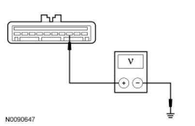
- Apply the brakes until the drive wheels come to a stop. Place the transmission in PARK (P), fully engage the parking brake and turn the engine OFF.
- Is the AC voltage greater than 4.5 volts?
Yes
GO to B5.
No
GO to B7.
-------------------------------------------------
B5 CHECK THE VEHICLE SPEED SIGNAL FREQUENCY
NOTICE: Make sure the vehicle is secured correctly before attempting to place the transmission range selector lever in DRIVE (D), or in 1st gear, if equipped with a manual transmission.
- NOTE: For vehicles equipped with a manual transmission, place the transmission into 1st gear.
- Start the vehicle, place the transmission in DRIVE (D), and with the engine at idle, allow the drive wheels to spin.
- Measure and record the frequency between the speed control actuator C122-3, circuit VMC05 (VT/OG), harness side and ground with the vehicle drive wheels spinning a minimum of 8 km/h (5 mph). Record the speedometer reading.
- Apply the brakes until the drive wheels come to a stop. Place the transmission in PARK (P), fully engage the parking brake and turn the engine OFF.
- Divide the frequency reading by 2.2 to get a mph result and compare this to the reading of the speedometer.
- Does the frequency reading result match the speedometer reading?
Yes
INSTALL a new speed control actuator. REFER to Speed Control Actuator Service and Repair. TEST the system for normal operation.
No
GO to B6.
-------------------------------------------------
B6 CHECK THE VEHICLE SPEED SIGNAL FOR A SHORT TO GROUND
- Measure the resistance between the speed control actuator C122-3, circuit VMC05 (VT/OG), harness side and ground.
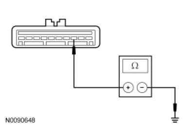
- Is the resistance greater than 10,000 ohms?
Yes
GO to B7.
No
REPAIR the circuit. REPEAT the self-test.
-------------------------------------------------
B7 CHECK FOR CORRECT PCM OPERATION
- Connect: All Disconnected Connectors.
- Disconnect the PCM connector.
- Check for:
- corrosion
- damaged pins
- pushed-out pins
- Connect the PCM connector and make sure it seats correctly.
- Operate the system and verify the concern is still present.
- Is the concern still present?
Yes
INSTALL a new PCM. TEST the system for normal operation.
No
The system is operating correctly at this time. The concern may have been caused by a loose or corroded connector.
-------------------------------------------------