Pinpoint Test E: Flash Code 3 - Speed Control Deactivator Switch Circuit Failure
Speed Control
Pinpoint Tests
Pinpoint Test E: Flash Code 3 - Speed Control Deactivator Switch Circuit Failure
Refer to wiring Diagram Set 31, Speed Control for schematic and connector information. Diagrams By Number
Normal Operation
The speed control deactivator switch receives voltage through circuit CBP26 (BU/WH). When the brake pedal is not applied, voltage is sent to the speed control actuator, from the speed control deactivator switch, through circuit CES09 (VT/OG). When the brake pedal is applied firmly, the speed control deactivator switch opens, removing the voltage signal from the speed control actuator and disabling the speed control.
This pinpoint test is intended to diagnose the following:
- Fuse
- Wiring, terminals or connectors
- Speed control deactivator switch
- Speed control actuator
PINPOINT TEST E: FLASH CODE 3 - SPEED CONTROL DEACTIVATOR SWITCH CIRCUIT FAILURE
NOTICE: Use the correct probe adapter(s) when making measurements. Failure to use the correct probe adapter(s) may damage the connectors.
-------------------------------------------------
E1 CHECK THE SPEED CONTROL DEACTIVATOR SWITCH SIGNAL
- Ignition OFF.
- Disconnect: Speed Control Actuator C122.
- Ignition ON.
- Measure the voltage between the speed control actuator C122-9, circuit CES09 (VT/OG), harness side and the speed control actuator C122-10, circuit GD123 (BK/GY), harness side.
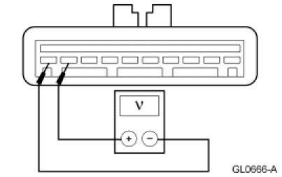
- Is the voltage greater than 10 volts?
Yes
INSTALL a new speed control actuator. REFER to Speed Control Actuator Service and Repair. REPEAT the self-test.
No
GO to E2.
-------------------------------------------------
E2 CHECK THE SPEED CONTROL DEACTIVATOR SWITCH VOLTAGE SUPPLY
- Ignition OFF.
- Disconnect: Speed Control Deactivator Switch C277.
- Ignition ON.
- Measure the voltage between the speed control deactivator switch C277-1, circuit CBP26 (BU/WH), harness side and ground.
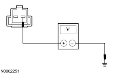
- Is the voltage greater than 10 volts?
Yes
GO to E3.
No
VERIFY the SJB fuse 26 (2A) is OK. If OK, REPAIR the circuit. REPEAT the self-test. If not OK, REFER to the Wiring Diagrams to identify the possible causes of the circuit short.
-------------------------------------------------
E3 CHECK THE SPEED CONTROL DEACTIVATOR SWITCH SIGNAL CIRCUIT FOR AN OPEN
- Ignition OFF.
- Measure the resistance between the speed control actuator C122-9, circuit CES09 (VT/OG), harness side and the speed control deactivator switch C277-2, circuit CES09 (VT/OG), harness side.
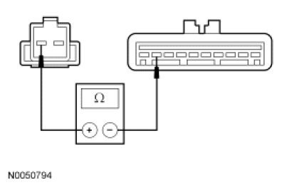
- Is the resistance less than 5 ohms?
Yes
INSTALL a new speed control deactivator switch. REFER to Speed Control Deactivator Switch Speed Control Deactivator Switch. REPEAT the self-test.
No
REPAIR the circuit. REPEAT the self-test.
-------------------------------------------------