Pinpoint Test F: Flash Code 4 - Vehicle Speed Signal Circuit Failure
Speed Control
Pinpoint Tests
Pinpoint Test F: Flash Code 4 - Vehicle Speed Signal Circuit Failure
Refer to wiring Diagram Set 31, Speed Control for schematic and connector information. Diagrams By Number
Normal Operation
The vehicle speed signal is sent from the PCM to the speed control actuator through circuit VMC05 (VT/OG).
This pinpoint test is intended to diagnose the following:
- Wiring, terminals or connectors
- Speed control actuator
PINPOINT TEST F: FLASH CODE 4 - VEHICLE SPEED SIGNAL CIRCUIT FAILURE
NOTICE: Use the correct probe adapter(s) when making measurements. Failure to use the correct probe adapter(s) may damage the connectors.
-------------------------------------------------
F1 CHECK THE SPEEDOMETER OPERATION
- Check the speedometer for correct operation by driving the vehicle.
- Does the speedometer operate correctly?
Yes
GO to F2.
No
REFER to Instrument Panel, Gauges and Warning Indicators to continue diagnosis of the speedometer.
-------------------------------------------------
F2 CHECK THE VEHICLE SPEED SIGNAL FOR A SHORT TO GROUND
- Measure the resistance between the speed control actuator C122-3, circuit VMC05 (VT/OG), harness side and ground.
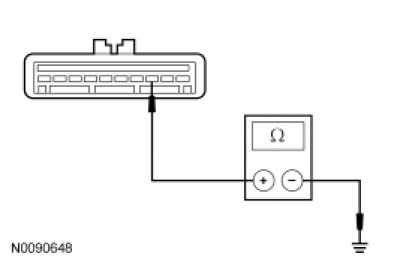
- Is the resistance greater than 10,000 ohms?
Yes
GO to F3.
No
REPAIR the circuit. REPEAT the self-test.
-------------------------------------------------
F3 CHECK THE VEHICLE SPEED SIGNAL CIRCUIT FOR AN OPEN
- Ignition OFF.
- Disconnect: Speed Control Actuator C122.
- Disconnect: PCM C175b.
- Measure the resistance between the PCM C175b-1, circuit VMC05 (VT/OG), harness side and the speed control actuator C122-3, circuit VMC05 (VT/OG), harness side.
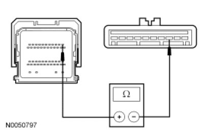
- Is the resistance less than 5 ohms?
Yes
INSTALL a new speed control actuator. REFER to Speed Control Actuator Service and Repair. REPEAT the self-test.
No
REPAIR the circuit. REPEAT the self-test.
-------------------------------------------------