Pinpoint Test
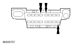
- CHECK THE Data Link Connector (DLC) PINS FOR DAMAGE
- Ignition OFF.
- Disconnect the scan tool cable from the Data Link Connector (DLC).
- Inspect Data Link Connector (DLC) pins 4, 5 and 16 for damage.
 Courtesy of FORD MOTOR CO.
- Are Data Link Connector (DLC) pins 4, 5 and 16 OK?
- Yes:
GO to 2
on page 2.
- No:
REPAIR the Data Link Connector (DLC) as necessary.
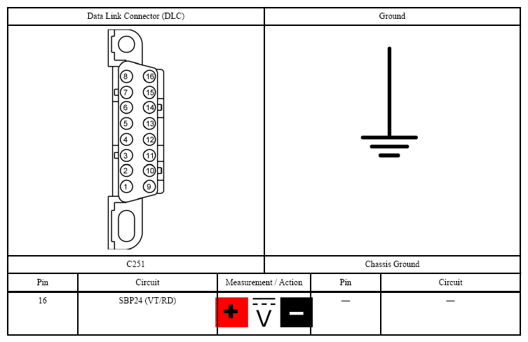
- CHECK THE Data Link Connector (DLC) VOLTAGE SUPPLY FOR AN OPEN
- Measure:
 Courtesy of FORD MOTOR CO.
- Is the voltage greater than 11 volts?
- Yes:
GO to 3
on page 3.
- No:
VERIFY the Body Control Module (BCM) fuse 24 (15A) is OK. If OK, REPAIR the circuit. If not OK,
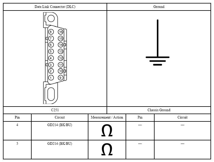
- CHECK THE Data Link Connector (DLC) GROUND CIRCUITS FOR AN OPEN
- Disconnect: Negative Battery Cable.
- Measure:
 Courtesy of FORD MOTOR CO.
- Are the resistances less than 3 ohms?
- Yes:
REPAIR the scan tool. CONNECT the negative battery cable.
- No:
REPAIR the circuit in question. CONNECT the negative battery cable.