Pinpoint Test
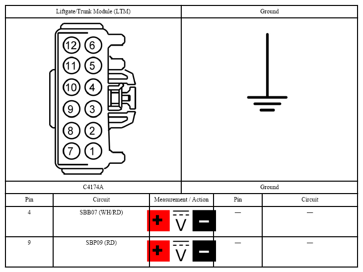
- CHECK THE Liftgate/Trunk Module (LTM) VOLTAGE SUPPLY CIRCUITS FOR AN OPEN
- Ignition OFF.
- Disconnect: Liftgate/Trunk Module (LTM) C4174A.
- Ignition ON.
- Measure:
 Courtesy of FORD MOTOR CO.
- Are the voltages greater than 11 volts?
- Yes:
GO to 2
on page 2.
- No:
VERIFY the Battery Junction Box (BJB) fuse 7 (30A) and the Body Control Module (BCM) fuse 9 (10A) is OK. If OK, REPAIR the circuit in question. If not OK, REFER to the SYSTEM WIRING DIAGRAMS
to identify the possible causes of the circuit short.
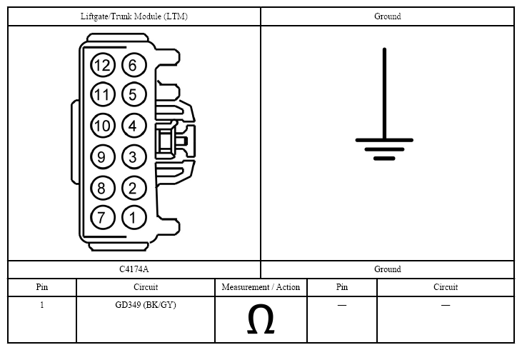
- CHECK THE Liftgate/Trunk Module (LTM) GROUND CIRCUIT FOR AN OPEN
- Ignition OFF.
- Measure:
 Courtesy of FORD MOTOR CO.
- Is the resistance less than 3 ohms?
- Yes:
GO to 3
on page 3.
- No:
REPAIR the circuit.
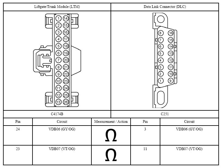
- CHECK THE Medium Speed Controller Area Network (MS-CAN) CIRCUITS BETWEEN THE Liftgate/Trunk Module (LTM) AND THE Data Link Connector (DLC) FOR AN OPEN
- Disconnect: Liftgate/Trunk Module (LTM) C4174B.
- Measure:
 Courtesy of FORD MOTOR CO.
- Are the resistances less than 3 ohms?
- Yes:
GO to 4
on page 4.
- No:
REPAIR the circuit in question.
- CHECK FOR CORRECT Liftgate/Trunk Module (LTM) OPERATION
- Ignition OFF.
- Disconnect and inspect the Liftgate/Trunk Module (LTM) connectors.
- Repair:
- corrosion (replace connector or terminals - clean module pins)
- damaged or bent pins - replace terminals/pins
- pushed-out pins - replace pins as necessary
- Reconnect the Liftgate/Trunk Module (LTM) connectors. Make sure they seat and latch correctly.
- Operate the system and verify the concern is still present.
- Is the concern still present?
- Yes:
CHECK On-Line Automotive Service Information System (OASIS) for any applicable Technical Service Bulletins (TSBs). If a Technical Service Bulletin (TSB) exists for this concern, discontinue this test and follow Technical Service Bulletin (TSB) instructions. If no Technical Service Bulletins (TSBs) address this concern, INSTALL a new Liftgate/Trunk Module (LTM). REFER to LIFTGATE/TRUNK MODULE (LTM) .
- No:
The system is operating correctly at this time. Concern may have been caused by a loose or corroded connector.