Pinpoint Test
- CHECK THE BATTERY
- Check the battery condition and state of charge. REFER to Diagnostic Routine A .
- Yes:
GO to step 2
.
- No:
INSTALL a new battery. REFER to BATTERY
.
- CHECK FOR ANY MESSAGES IN THE MESSAGE CENTER
- Check the message center while holding the ignition key in the start position.
- Is STARTING SYSTEM FAULT displayed in the message center?
- CHECK THE IN GEAR-TRANSMISSION IS APPLYING A LOAD TO ENGINE (IN_GEAR) Parameter Identification (PID).
- Using a scan tool, view the Powertrain Control Module (PCM) Parameter Identifications (PIDs).
- While observing the Powertrain Control Module (PCM) Parameter Identification (PID) IN_GEAR, place the gear selector in PARK and then NEUTRAL.
- Does the Parameter Identification (PID) read NO in both positions?
- RETRIEVE Powertrain Control Module (PCM) Diagnostic Trouble Codes (DTCs)
- Ignition ON.
- Using a scan tool, perform the Powertrain Control Module (PCM) self-test.
- Were Diagnostic Trouble Codes (DTCs) retrieved on-demand during self-test?
- CHECK THE ENGINE CRANKING (ENG_CRANK) Parameter Identification (PID)
- Using a scan tool, view the Powertrain Control Module (PCM) Parameter Identifications (PIDs).
- While holding the key in the START position, monitor the Powertrain Control Module (PCM) Parameter Identification (PID) ENG_CRANK.
- Does the Parameter Identification (PID) change from Inactive to Active?
- Yes:
GO to step 6
.
- No:
GO to step 16
.
- CHECK THE STARTER RELAY
- Swap the starter relay with a known good relay and attempt to crank the engine.
- Yes:
INSTALL a new starter relay.
- No:
GO to step 7
.
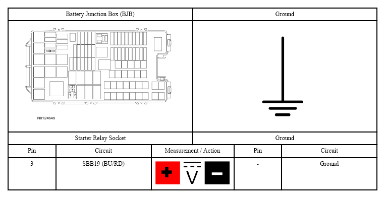
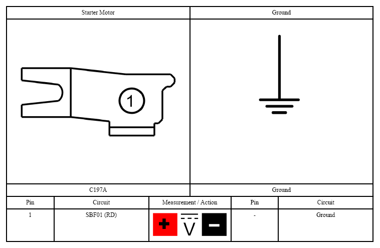
- CHECK THE VOLTAGE TO THE STARTER RELAY
- Ignition OFF.
- Disconnect: Starter Relay.
- Measure:
 Courtesy of FORD MOTOR CO.
- Is the voltage greater than 11 volts?
- Yes:
GO to step 8
.
- No:
VERIFY Battery Junction Box (BJB) fuse 19 (30A) is OK. If OK, REPAIR the circuit for an open. If not OK, REFER to the SYSTEM WIRING DIAGRAMS
to identify the possible causes of the circuit short.
- CHECK THE STARTER MOTOR
- With the gear selector in PARK, connect a fused jumper wire:
 Courtesy of FORD MOTOR CO.
- Did the starter motor engage and the engine crank?
- Yes:
GO to step 14
.
- No:
GO to step 9
.
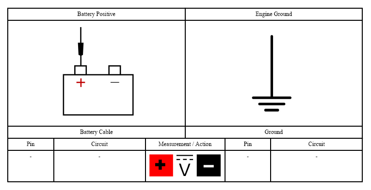
- CHECK THE BATTERY GROUND CABLE
- Measure:
 Courtesy of FORD MOTOR CO.
- Is the voltage greater than 11 volts?
- CHECK THE STARTER MOTOR GROUND
- Measure:
 Courtesy of FORD MOTOR CO.
- Is the voltage greater than 11 volts?
- Yes:
GO to step 11
.
- No:
CLEAN the starter motor mounting flange and make sure the starter motor is correctly mounted.
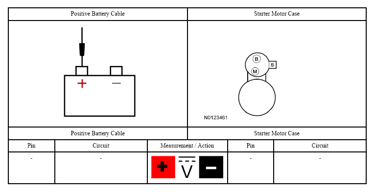
- CHECK THE VOLTAGE TO THE STARTER MOTOR
- Measure:
 Courtesy of FORD MOTOR CO.
- Is the voltage greater than 11 volts?
- CHECK THE STARTER MOTOR
- Connect a fused jumper wire:
 Courtesy of FORD MOTOR CO.
- Did the starter engage and the engine crank?
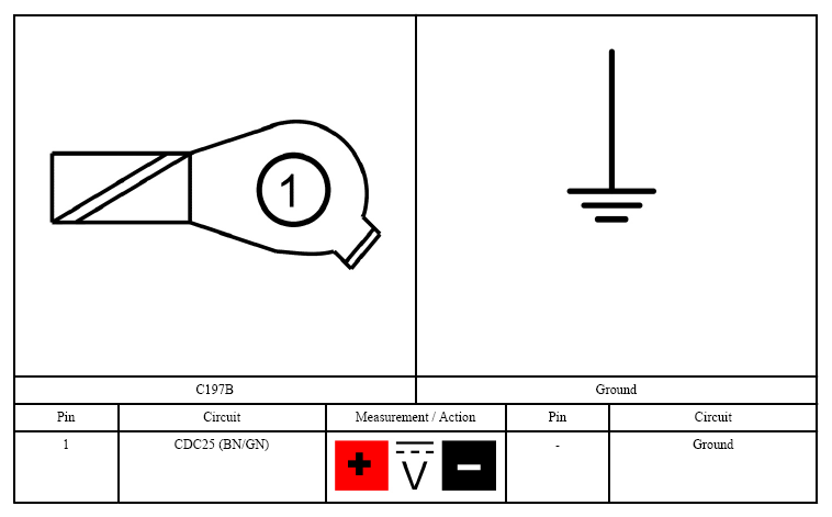
- CHECK FOR START INPUT AT THE STARTER
- Connect: Starter Relay.
- Disconnect: Starter Solenoid C197B.
- While holding the key in the START position, measure:
 Courtesy of FORD MOTOR CO.
- Is the voltage greater than 11 volts?
- Yes:
CLEAN the starter solenoid "S" terminal and C197B. CHECK the wiring and the starter motor for a loose or intermittent connection.
- No:
REPAIR the circuit for an open.
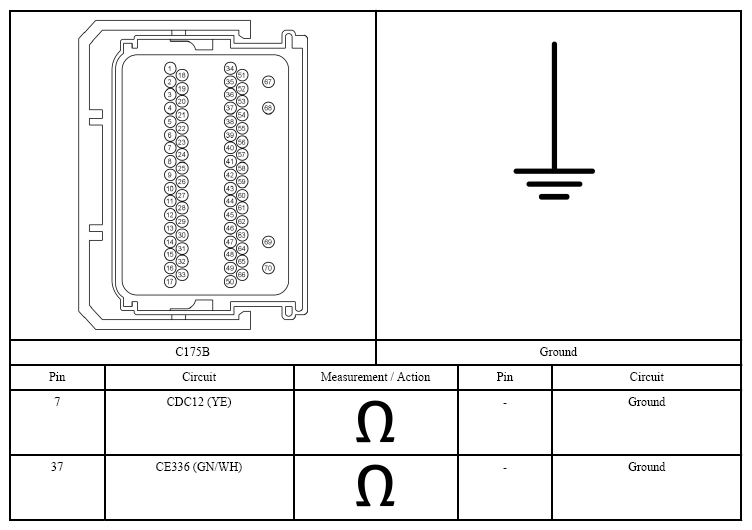
- CHECK THE Powertrain Control Module (PCM) START CIRCUITS FOR A SHORT TO GROUND
- Ignition OFF.
- Disconnect: Powertrain Control Module (PCM) C175B.
- Measure:
 Courtesy of FORD MOTOR CO.
- Are the resistances to ground greater than 10,000 ohms?
- Yes:
GO to step 15
.
- No:
REPAIR the affected circuit for a short to ground.
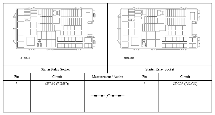
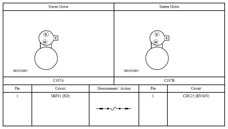
- CHECK THE Powertrain Control Module (PCM) START CIRCUITS FOR AN OPEN
- Measure:
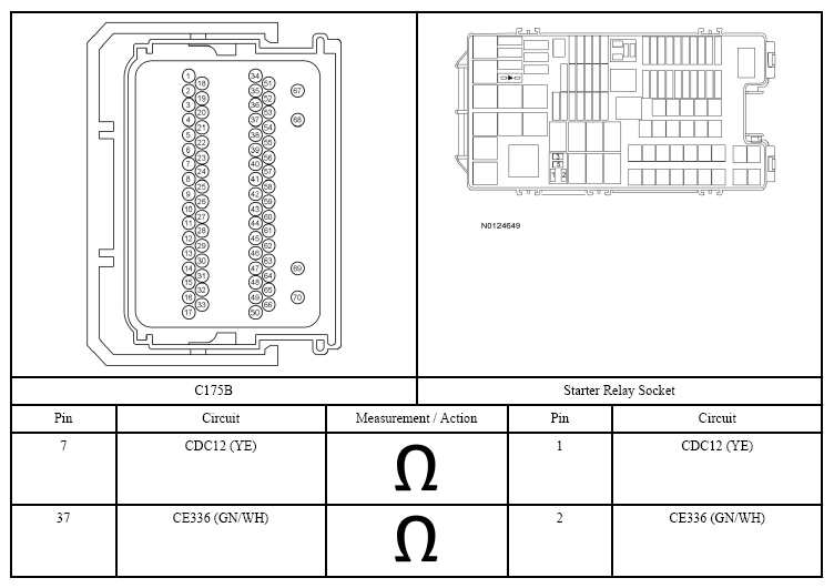 Courtesy of FORD MOTOR CO.
- Are the resistances less than 3 ohms?
- Yes:
GO to step 18
.
- No:
REPAIR the affected circuit for an open.
- CHECK THE START CIRCUIT FOR VOLTAGE AT THE Powertrain Control Module (PCM)
- Ignition OFF.
- Disconnect: Powertrain Control Module (PCM) C175B.
- While holding the key in the START position, measure:
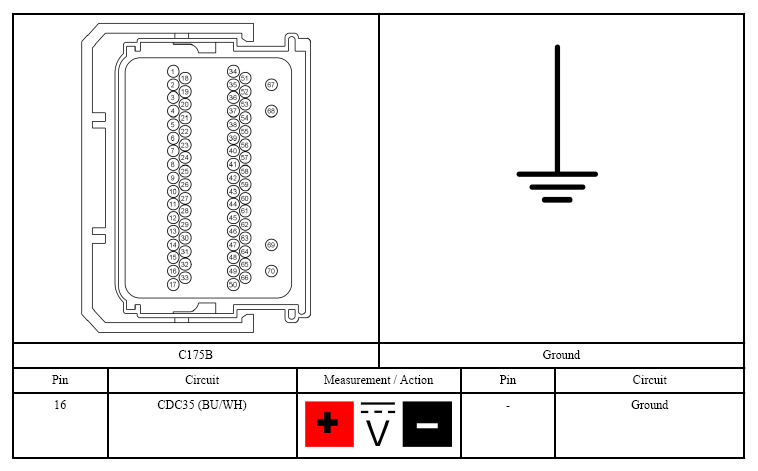 Courtesy of FORD MOTOR CO.
- Is the voltage greater than 11 volts?
- Yes:
GO to step 18
.
- No:
GO to step 17
.
- CHECK THE IGNITION SWITCH
- Carry out the Ignition Switch Component Test. Refer to SYSTEM WIRING DIAGRAMS
for component testing.
- Did the ignition switch pass the component test?
- Yes:
REPAIR the circuit for an open.
- No:
INSTALL a new ignition switch. REFER to Ignition Switch .
- CHECK FOR CORRECT Powertrain Control Module (PCM) OPERATION
- Ignition OFF.
- Disconnect and inspect all Powertrain Control Module (PCM) connectors.
- Repair:
- corrosion (install new connector or terminals - clean module pins)
- damaged or bent pins - install new terminals/pins
- pushed-out pins - install new pins as necessary
- Reconnect the Powertrain Control Module (PCM) connectors. Make sure they seat and latch correctly.
- Operate the system and determine if the concern is still present.
- Is the concern still present?
- Yes:
CHECK On-Line Automotive Service Information System (OASIS) for any applicable Technical Service Bulletins (TSBs). If a Technical Service Bulletin (TSB) exists for this concern, DISCONTINUE this test and FOLLOW the Technical Service Bulletin (TSB) instructions. If no Technical Service Bulletin (TSB) address this concern, INSTALL a new Powertrain Control Module (PCM). REFER to Powertrain Control Module (PCM) .
- No:
The system is operating correctly at this time. The concern may have been caused by module connections. ADDRESS the root cause of any connector or pin issues.