Cylinder Head Assembly
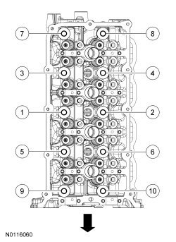
Cylinder HeadTighten the new RH cylinder head bolts in 4 stages in the sequence shown.
Stage 1: Tighten to 25 Nm (18 lb-ft).
Stage 2: Tighten to 40 Nm (30 lb-ft).
Stage 3: Tighten an additional 90 degrees.
Stage 4: Tighten an additional 90 degrees.
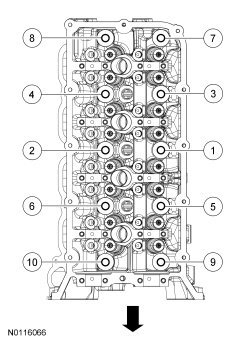
Tighten the new LH cylinder head bolts in 4 stages in the sequence shown.
Stage 1: Tighten to 25 Nm (18 lb-ft).
Stage 2: Tighten to 40 Nm (30 lb-ft).
Stage 3: Tighten an additional 90 degrees.
Stage 4: Tighten an additional 90 degrees.
Bolt Re-usability
NOTE: The cylinder head bolts must be discarded and new bolts installed. They are a tighten-to-yield design and cannot be reused.
Surface Variation -- Head-to-Block, Head-to-Manifolds and Surface Variation -- Warpage


a Time required for the plunger to leak down 1.6 mm of travel with 222 N force and leakdown fluid in the lash adjuster.
b Before Grafal coating.
Camshaft Bearing Cap
Camshaft - LH
Tighten the bolts in the sequence shown in 2 stages.
Stage 1: Tighten to 6 Nm (53 lb-in).
Stage 2: Tighten an additional 45 degrees.
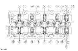
Camshaft - RH
Tighten the bolts in the sequence shown in 2 stages.
Stage 1: Tighten to 6 Nm (53 lb-in).
Stage 2: Tighten an additional 45 degrees.
Intake Manifold Specifications
Exhaust Manifold Specifications