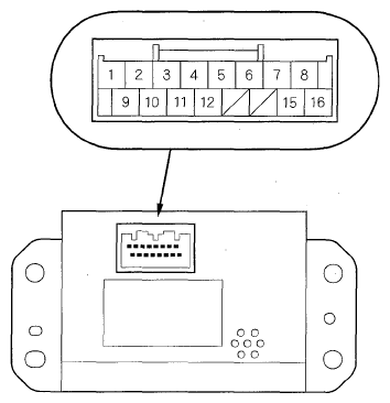
Active Noise Control Unit Connector for Inputs and Outputs
When replacing an active noise control unit connector, match the wires to the cavities listed in the following table.
 Courtesy of AMERICAN HONDA MOTOR CO., INC.
 WIRE CAVITY CHART
| Cavity |
Wire |
Connects to |
| 1 |
PNK |
Stereo amplifier (R+) |
| 2 |
PUR |
Stereo amplifier (F+) |
| 3 |
LTGRN |
Active noise control front microphone (MIC F IN+) |
| 4 |
RED |
Stereo amplifier, Active noise control rear microphone (MIC R IN+) |
| 5 |
BLU |
Stereo amplifier, Active noise control rear microphone (MIC R IN-) |
| 6 |
GRY |
Stereo amplifier (REMOTE ON) |
| 7 |
BLK |
Ground (G652) |
| 8 |
PUR |
Active noise control power supply (ACC) |
| WHT |
Constant power (+B) |
| 9 |
GRN |
Stereo amplifier (R-) |
| 10 |
ORN |
Stereo amplifier (F-) |
| 11 |
LTBLU |
Active noise control front microphone (MIC F IN-) |
| 12 |
WHT |
Stereo amplifier (DIAG) |
| 15 |
GRN |
PCM, Test tachometer connector (NEP) |
| 16 |
PNK |
Multiplex integrated control unit (MICU) (INTR LT-) |