Audio Unit Connector C (28P)
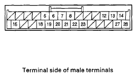 Courtesy of AMERICAN HONDA MOTOR CO., INC.
Audio Unit Connector C (28P)
Audio Unit Connector C (28P) TERMINAL REFERENCE
| Cavity |
Wire |
Connects to |
| C5 |
ORN |
Audio-HVAC subdisplay unit (PNL CE) |
| C6 |
GRY |
Audio-HVAC subdisplay unit(PNL SH1) |
| C7 |
BRN |
Audio-HVAC subdisplay unit (PNL 5VGND) |
| C8 |
ORN |
Audio-HVAC subdisplay unit (LCD BL-) |
| C12 |
LT BLU |
HandsFreeLink control unit (HFL ICON) |
| C13 |
RED |
HandsFreeLink control unit (TELM SIG-) |
| C14 |
GRY |
HandsFreeLink control unit (TELM SIG SH) |
| C15 |
LT GRN |
Climate control unit (AC-SO2) |
| C18 |
YEL |
Audio-HVAC subdisplay unit(PNL DATA1) |
| C19 |
BLU |
Audio-HVAC subdisplay unit (PNL RST) |
| C20 |
PUR |
Audio-HVAC subdisplay unit (PNL CLK) |
| C21 |
RED |
Audio-HVAC subdisplay unit (PNL +5V) |
| C22 |
GRN |
Audio-HVAC subdisplay unit (LCD BL+) |
| C23 |
PUR |
AcuraLink control unit (XM receiver) (HIP MUTE) |
| C27 |
GRN |
HandsFreeLink control unit (TELM SIG+) |
| C28 |
LT GRN |
HandsFreeLink control unit (HFL MUTE) |
 Courtesy of AMERICAN HONDA MOTOR CO., INC.
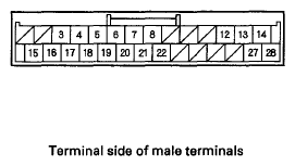
Audio Unit Connector C (28P)
Audio Unit Connector C (28P) TERMINAL REFERENCE
| Cavity |
Wire |
Connects to |
| C3 |
PUR |
Audio switch panel (ENCORDER-) |
| C4 |
BLK |
Audio switch panel (PNL DATA2) |
| C5 |
YEL |
Audio switch panel (PNLCE) |
| C6 |
GRY |
Audio switch panel (PNLSH1) |
| C7 |
BRN |
Audio switch panel (PNL 5V GND) |
| C8 |
ORN |
Audio-HVAC display unit (LCD BL-) |
| C12 |
LT BLU |
HandsFreeLink control unit (HFL ICON) |
| C13 |
RED |
HandsFreeLink control unit(TELM SIG-) |
| C14 |
GRY |
HandsFreeLink control unit(TELM SIG SH) |
| C15 |
LT GRN |
Climate control unit (AC-SO2) |
| C16 |
GRY |
Audio switch panel (PNL SH2) |
| C17 |
LT BLU |
Audio switch panel (ENCORDER+) |
| C18 |
RED |
Audio switch panel (PNLDATA1) |
| C19 |
GRN |
Audio switch panel (PNL RST) |
| C20 |
WHT |
Audio switch panel (PNLCLK) |
| C21 |
RED |
Audio switch panel (PNL+5V) |
| C22 |
GRN |
Audio-HVAC display unit (LCD BL+) |
| C27 |
GRN |
HandsFreeLink control unit(TELMSIG+) |
| C28 |
LT GRN |
HandsFreeLink control unit (HFL MUTE) |