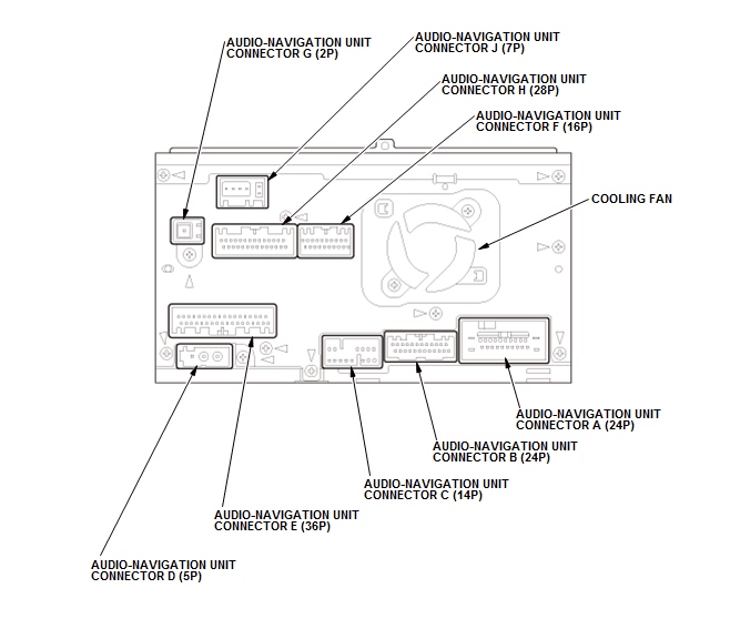
Audio-Navigation Unit Connector for Inputs and Outputs (2013-15)
Audio-Navigation Unit Connector for Inputs and Outputs
 Courtesy of HONDA, U.S.A., INC. Courtesy of HONDA, U.S.A., INC.
|
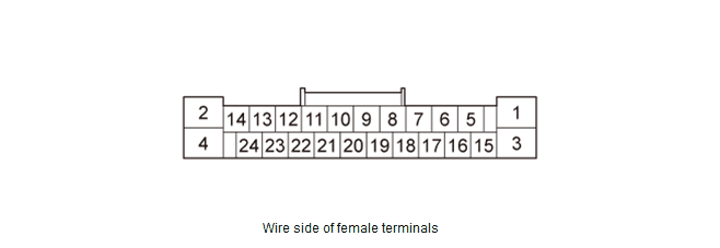
AUDIO-NAVIGATION UNIT CONNECTOR A (24P)
 Courtesy of HONDA, U.S.A., INC. Courtesy of HONDA, U.S.A., INC.
|
| Cavity |
Wire Color |
Terminal Name |
Description |
Voltage (about) |
Symptom |
| A1 |
BLK |
GND |
Ground for audio-navigation unit (G504) |
0 V |
If open: Navigation screen goes black (backlight still operates). Audio system does not work.If short to ground: No effect on system. |
| A2 |
YEL |
ILL- (LED) |
Detects illumination control signal |
Lights on:0 V - battery voltage (depends on dash brightness) |
If open/short: When brightness=Auto, night mode for the display is inoperative when lights on. Diagnostic screen Car Status, ILL CANCEL = 0. |
| A3 |
GRN |
+B BACK UP |
Continuous power source |
Battery voltage |
If open: Navigation screen goes black (backlight still operates). Audio system does not work.If short to ground: Blows the No. A29 (10 A) fuse in the under-hood fuse/relay box. |
| A4 |
GRY |
ILLUMI+ |
Detects parking light on signal |
Lights on:battery voltage, Lights off: 0 V |
If open: When brightness=Auto, night mode for the display is inoperative when lights on. Diagnostic screen Car Status, ILL = 0.If short to ground: Blows the No. B35 (7.5 A) fuse in the under-dash fuse/relay box. |
| A5 |
YEL |
RL PRE+ (ELS) |
Outputs sound signal for left rear channel |
- - - |
- - - |
| A6 |
PUR |
RL PRE- (ELS) |
Outputs sound signal for left rear channel |
- - - |
- - - |
| A7 |
GRY |
SH RR PRE (ELS) |
Shield for terminals No. 5 and No. 6 |
- - - |
- - - |
| A8 |
Not used |
Not used |
- - - |
- - - |
- - - |
| A9 |
ORN |
RR PRE + (ELS) |
Outputs sound signal for Right rear channel |
- - - |
- - - |
| A10 |
BLU |
RR PRE- (ELS) |
Outputs sound signal for Right rear channel |
- - - |
- - - |
| A11 |
BRN |
REMOTE SW GND |
Audio remote-HFL switch ground |
0 V |
- - - |
| A12 |
BRN |
SCTY RADIO SW2 |
Security signal from MICU |
- - - |
If open: The security system sets. |
| A13 |
LT BLU |
K LINE |
Detects scan tool signal (serial data) |
- - - |
- - - |
| A14 |
Not used |
Not used |
- - - |
- - - |
- - - |
| A15 |
WHT |
FL PRE+ (ELS) |
Outputs sound signal for left front channel |
- - - |
- - - |
| Cavity |
Wire Color |
Terminal Name |
Description |
Voltage (about) |
Symptom |
| A16 |
BLK |
FL PRE- (ELS) |
Outputs sound signal for left front channel |
- - - |
- - - |
| A17 |
GRY |
SH FR PRE (ELS) |
Shield for terminals No. 15 and No. 16 |
- - - |
- - - |
| A18 |
Not used |
Not used |
- - - |
- - - |
- - - |
| A19 |
RED |
FR PRE+ (ELS) |
Outputs sound signal for right front speakers |
- - - |
- - - |
| A20 |
GRN |
FR PRE- (ELS) |
Outputs sound signal for right front speakers |
- - - |
- - - |
| A21 |
YEL |
SWD +B |
Outputs signal for stereo amplifier switching on/off |
Vehicle is in ACC mode: 10.5 V |
- - - |
| A22 |
PNK |
AUDIO REMOTE SW |
Detects control signal from audio remote switch |
- - - |
- - - |
| A23 |
BLU |
VSP |
Detects vehicle speed pulse from PCM |
Vehicle is in ACC mode: 5 V Vehicle is in ON mode: Pulses (depends on vehicle speed) |
If open/short: No vehicle speed pulse. Diagnostic screen Car Status, VSP = 0. |
| A24 |
PUR |
ACC |
Power source for accessories |
Vehicle is in ACC mode: Battery voltage |
If open: Navigation screen goes black (backlight still operates). Audio system does not work.If short to ground: Blows the No. B19 (7.5 A) fuse in the under-dash fuse/relay box. |
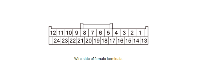
AUDIO-NAVIGATION UNIT CONNECTOR B (24P)
 Courtesy of HONDA, U.S.A., INC. Courtesy of HONDA, U.S.A., INC.
|
| Cavity |
Wire Color |
Terminal Name |
Description |
Voltage (about) |
Symptom |
| B1 |
PNK |
SUB W PRE+ (ELS) |
Outputs sound signal for subwoofer channel |
- - - |
- - - |
| B2 |
GRY |
SH CTR SUB W PRE (ELS) |
Shield for terminals No. 1, No. 3, No. 4, and No. 13 |
- - - |
- - - |
| B3 |
LT GRN |
CTR PRE+ (ELS) |
Outputs sound signal for center channel |
- - - |
- - - |
| B4 |
BRN |
CTR PRE- (ELS) |
Outputs sound signal for center channel |
- - - |
- - - |
| B5 |
Not used |
Not used |
- - - |
- - - |
- - - |
| B6 |
Not used |
Not used |
- - - |
- - - |
- - - |
| B7 |
Not used |
Not used |
- - - |
- - - |
- - - |
| B8 |
GRN |
TELEM SIG + |
Inputs HFL prompts and telephone sound signal from HandsFreeLink control unit |
- - - |
- - - |
| B9 |
Not used |
Not used |
- - - |
- - - |
- - - |
| B10 |
PUR |
AUX DET |
Detects connection signal for auxiliary jack assembly |
- - - |
- - - |
| B11 |
PNK |
AUX SGND |
Ground for sound signal from auxiliary jack assembly |
- - - |
- - - |
| B12 |
BLU |
AUX L CH |
Inputs sound signal from auxiliary jack assembly |
- - - |
- - - |
| B13 |
LT BLU |
SUB W PRE - (ELS) |
Outputs sound signal for subwoofer channel |
- - - |
- - - |
| B14 |
Not used |
Not used |
- - - |
- - - |
- - - |
| B15 |
BLU |
NAVI GND |
Ground for voice guidance and Voice Recognition (VR) prompts |
0 V |
If open: If navi voice activated, speakers buzz; if voice off, no effect.If short to ground: No effect on voice output. |
| B16 |
GRY |
NAVI CH SH |
Shield for terminals No. 15 and No. 17 |
0 V |
If open/short to ground: No effect on voice output. |
| Cavity |
Wire Color |
Terminal Name |
Description |
Voltage (about) |
Symptom |
| B17 |
PNK |
NAVI LCH |
Outputs front audio signal of voice guidance and Voice Recognition (VR) prompts |
Audio signal0.004 - 0.04 V (depends on navi voice out) |
If open/short: If navi voice activated, speakers buzz; if voice off, no effect. |
| B18 |
Not used |
Not used |
- - - |
- - - |
- - - |
| B19 |
Not used |
Not used |
- - - |
- - - |
- - - |
| B20 |
GRY |
SH TELEM SIG |
Shield for terminals No. 8 and No. 21 |
- - - |
- - - |
| B21 |
RED |
TELEM SIG - |
Inputs HFL prompts and telephone sound signal from HandsFreeLink control unit |
- - - |
- - - |
| B22 |
GRY |
SH AUX |
Shield for terminals No. 11, No. 12, and No. 24 |
- - - |
- - - |
| B23 |
YEL |
AUX GND |
Ground for auxiliary jack assembly |
- - - |
- - - |
| B24 |
GRN |
AUX R CH |
Inputs sound signal from auxiliary jack assembly |
- - - |
- - - |
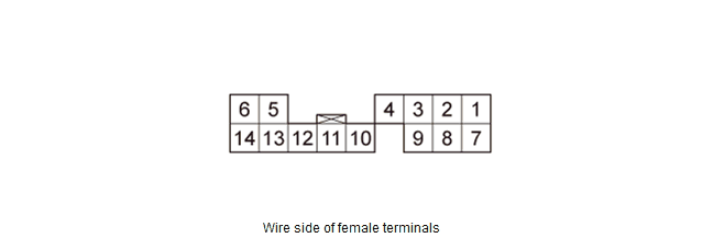
AUDIO-NAVIGATION UNIT CONNECTOR C (14P)
 Courtesy of HONDA, U.S.A., INC. Courtesy of HONDA, U.S.A., INC.
|
| Cavity |
Wire Color |
Terminal Name |
Description |
Voltage (about) |
Symptom |
| C1 |
BLK |
GA AUDIO L+ |
Inputs sound signal from GA-Net related units |
- - - |
- - - |
| Cavity |
Wire Color |
Terminal Name |
Description |
Voltage (about) |
Symptom |
| C2 |
RED |
GA AUDIO R+ |
Inputs sound signal from GA-Net related units |
- - - |
- - - |
| C3 |
GRY |
SH GA AUDIO |
Shield for terminals No. 1, No. 2, No. 7, and No. 8 |
- - - |
- - - |
| C4 |
GRY |
SH GA BUS |
Shield for terminals No. 11 and No. 12 |
0 V |
If open/short to ground: No effect on system. |
| C5 |
YEL |
GA SYS ON |
Output signal for GA-Net related units switching on/off |
Vehicle is in ACC mode: 0 VVehicle is in OFF mode: Battery voltage |
If open: System Link screen XM and HFL icon shows red.If short to ground: No effect on system. |
| C6 |
RED |
GA +B |
Outputs power source for GA-Net related units |
Battery voltage |
If open/short: System Link screen XM and HFL icon shows red. |
| C7 |
GRN |
GA AUDIO L - |
Inputs sound signal from GA-Net related units |
- - - |
- - - |
| C8 |
WHT |
GA AUDIO R - |
Inputs sound signal from GA-Net related units |
- - - |
- - - |
| C9 |
Not used |
Not used |
- - - |
- - - |
- - - |
| C10 |
BRN |
GA GND |
GA-Net related units ground |
0 V |
If open: System Link screen XM and HFL icon shows red.If short to ground: No effect on system. |
| C11 |
PUR |
GA BUS - |
GA-Net bus communication signal |
Vehicle is in ACC mode: Pulses (depends on bus traffic) |
If open/short: Navigation screen goes black (backlight still operates). |
| C12 |
LT BLU |
GA BUS + |
GA-Net bus communication signal |
Vehicle is in ACC mode: Pulses (depends on bus traffic) |
If open/short: Navigation screen goes black (backlight still operates). |
| C13 |
Not used |
Not used |
- - - |
- - - |
- - - |
| C14 |
Not used |
Not used |
- - - |
- - - |
- - - |
AUDIO-NAVIGATION UNIT CONNECTOR D (5P)
 Courtesy of HONDA, U.S.A., INC. Courtesy of HONDA, U.S.A., INC.
|
| Cavity |
Wire Color |
Terminal Name |
Description |
Voltage (about) |
Symptom |
| D1 |
- - - |
SWD +B |
Power source for AM/FM/XM antenna |
- - - |
- - - |
| D2 |
- - - |
AM/FM |
Inputs AM/FM signal |
- - - |
- - - |
| D3 |
Not used |
Not used |
- - - |
- - - |
- - - |
| D4 |
- - - |
SH (AM/FM) |
Shield for terminal No. 2 |
- - - |
- - - |
| D5 |
Not used |
Not used |
- - - |
- - - |
- - - |
AUDIO-NAVIGATION UNIT CONNECTOR E (36P)
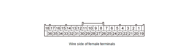 Courtesy of HONDA, U.S.A., INC. Courtesy of HONDA, U.S.A., INC.
|
| Cavity |
Wire Color |
Terminal Name |
Description |
Voltage (about) |
Symptom |
| E1 |
Not used |
Not used |
- - - |
- - - |
- - - |
| E2 |
Not used |
Not used |
- - - |
- - - |
- - - |
| E3 |
Not used |
Not used |
- - - |
- - - |
- - - |
| E4 |
LT GRN |
CAMERA BIT0 |
Mode select signal for rearview camera |
0 - 7 V (depends on rearview mode) |
If open/short: No change to rearview camera image. |
| E5 |
GRN |
ANC CHK2 |
Outputs ANC test signal |
- - - |
- - - |
| E6 |
Not used |
Not used |
- - - |
- - - |
- - - |
| Cavity |
Wire Color |
Terminal Name |
Description |
Voltage (about) |
Symptom |
| E7 |
PNK |
B CAN-H |
Communication signal |
Vehicle is in ON mode: Pulses (depends on bus traffic) |
If open: System Link B-CAN icon shown as red.If short: Same diagnostic conditions as when open, and also sets the B-CAN DTC (B-CAN BUS OFF). |
| E8 |
Not used |
Not used |
- - - |
- - - |
- - - |
| E9 |
Not used |
Not used |
- - - |
- - - |
- - - |
| E10 |
Not used |
Not used |
- - - |
- - - |
- - - |
| E11 |
GRN |
AMP DATA + |
Communication signal to stereo amplifier |
- - - |
- - - |
| E12 |
RED |
AMP DATA - |
Communication signal to stereo amplifier |
- - - |
- - - |
| E13 |
GRY |
SH VOL ENC |
Shield for terminals No. 14, No. 31, and No. 32 |
- - - |
- - - |
| E14 |
GRN |
VOL ENC - |
Inputs volume encoder signal |
- - - |
- - - |
| E15 |
GRY |
SH OPERA |
Shield for terminals No. 16 and No. 34 |
- - - |
- - - |
| E16 |
YEL |
OPERA RX |
Communication signal for audio-navigation switch panel buttons |
- - - |
- - - |
| E17 |
GRY |
SH DUET |
Shield for terminals No. 18 and No. 36 |
- - - |
- - - |
| E18 |
RED |
DUET RX |
Communication signal for audio-navigation switch panel display |
- - - |
- - - |
| E19 |
Not used |
Not used |
- - - |
- - - |
- - - |
| E20 |
Not used |
Not used |
- - - |
- - - |
- - - |
| E21 |
Not used |
Not used |
- - - |
- - - |
- - - |
| E22 |
Not used |
Not used |
- - - |
- - - |
- - - |
| E23 |
YEL |
CAMERA BIT1 |
Mode select signal for rearview camera |
0 - 7 V (depends on rearview mode) |
If open/short: No change to rearview camera image. |
| E24 |
Not used |
Not used |
- - - |
- - - |
- - - |
| E25 |
Not used |
Not used |
- - - |
- - - |
- - - |
| Cavity |
Wire Color |
Terminal Name |
Description |
Voltage (about) |
Symptom |
| E26 |
Not used |
Not used |
- - - |
- - - |
- - - |
| E27 |
BLU |
B CAN-L |
Communication signal |
Vehicle is in ON mode: Pulses (depends on bus traffic) |
If open: System Link B-CAN icon shown as red.If short: Same diagnostic conditions as when open, and also sets the B-CAN DTC (B-CAN BUS OFF). |
| E28 |
Not used |
Not used |
- - - |
- - - |
- - - |
| E29 |
Not used |
Not used |
- - - |
- - - |
- - - |
| E30 |
GRY |
SH AMP DATA |
Shield for terminals No. 11 and No. 12 |
- - - |
- - - |
| E31 |
PNK |
PWR SW |
Inputs POWER switch on/off signal |
- - - |
- - - |
| E32 |
BLU |
VOL ENC + |
Inputs volume encoder signal |
- - - |
- - - |
| E33 |
GRN |
OPERA CONT |
OPERA control signal |
- - - |
- - - |
| E34 |
BRN |
OPERA TX |
Communication signal for audio-navigation switch panel buttons |
- - - |
- - - |
| E35 |
LT BLU |
DUET CONT |
DUET control signal |
- - - |
- - - |
| E36 |
GRN |
DUET TX |
Communication signal for audio-navigation switch panel display |
- - - |
- - - |
AUDIO-NAVIGATION UNIT CONNECTOR F (16P)
 Courtesy of HONDA, U.S.A., INC. Courtesy of HONDA, U.S.A., INC.
|
| Cavity |
Wire Color |
Terminal Name |
Description |
Voltage (about) |
Symptom |
| F1 |
WHT |
DISPLAY R |
Outputs red color signal |
0.7 V AC average in RGB color diagnostic mode |
If open: Red color missing (see RGB Color diagnosis).If short: Symptom same as open, or navigation screen goes black (backlight still operates). |
| F2 |
RED |
DISPLAY G |
Outputs green color signal |
0.7 V AC average in RGB color diagnostic mode |
If open: Green color missing (see RGB Color diagnosis).If short: Symptom same as open, or navigation screen goes black (backlight still operates). |
| F3 |
YEL |
DISPLAY B |
Outputs blue color signal |
0.7 V AC average in RGB color diagnostic mode |
If open: Blue color missing (see RGB Color diagnosis).If short: Symptom same as open, or navigation screen goes black (backlight still operates). |
| F4 |
BLK |
DISPLAY RGB GND |
Ground for color signals |
0 V |
If open/short: No effect on system. |
| F5 |
GRY |
SYSTEM GND |
Ground for Composite signal |
0 V |
If open/short to ground: No effect on system. |
| F6 |
Not used |
Not used |
- - - |
- - - |
- - - |
| F7 |
Not used |
Not used |
- - - |
- - - |
- - - |
| F8 |
Not used |
Not used |
- - - |
- - - |
- - - |
| F9 |
BRN |
DISPLAY VBS |
Composite video(vertical/horizontal)synchronizing signal |
0.3 V AC average in RGB color diagnostic mode |
If open: Picture rolls horizontally, colors still visible.If short: Symptom same as open, or navigation screen goes black (backlight still operates). |
| F10 |
GRN |
DISPLAY YS |
Overlay control signal |
1.0 V AC average (depends on display mode) |
If open/short: Rearview camera guide line does not display. |
| F11 |
BLU |
DISPLAY SYNC GND |
Ground for synchronizingsignal |
0 V |
If open/short: No effect on system. |
| F12 |
GRY |
SH DISPLAY RGB |
Shield for terminals No. 1, No. 2, No. 3, No. 4, No. 9, No. 10, and No. 11 |
0 V |
If open/short to ground: No effect on system. |
| F13 |
Not used |
Not used |
- - - |
- - - |
- - - |
| F14 |
PNK |
DISP GND |
Ground for Composite signal |
0 V |
If open: No effect on system. |
| F15 |
GRY |
BACK LT |
Reverse signal ofselect lever fromreverse relay circuit |
In R: battery voltageOtherwise: 0 V |
If open/short: When shift lever is in R, diagnostic screen Car Status, BACK = 0. |
| F16 |
Not used |
Not used |
- - - |
- - - |
- - - |
AUDIO-NAVIGATION UNIT CONNECTOR G (2P)
 Courtesy of HONDA, U.S.A., INC. Courtesy of HONDA, U.S.A., INC.
|
| Cavity |
Wire Color |
Terminal Name |
Description |
Voltage (about) |
Symptom |
| G1 |
- - - |
GPS SIG |
Inputs GPS signal |
Vehicle is in ACC mode: 5 V |
If open/short to ground: GPS icon on screen is not shown, System Link screen GPS Ant. shows red. |
| G2 |
- - - |
SH GPS SIG |
Shield for terminal No. 1 |
- - - |
If open/short to ground: GPS icon on screen is not shown, System Link screen GPS Ant. shows red. |
AUDIO-NAVIGATION UNIT CONNECTOR H (28P)
 Courtesy of HONDA, U.S.A., INC. Courtesy of HONDA, U.S.A., INC.
|
| Cavity |
Wire Color |
Terminal Name |
Description |
Voltage (about) |
Symptom |
| H1 |
GRY |
SH HFT-NAVI MIC |
Shield for terminals No. 15 and No. 16 |
0 V |
If open/short to ground: No effect on system. |
| H2 |
GRY |
SH JOG |
Shield for terminal No. 17 |
0 V |
If open/short to ground: No effect on system. |
| H3 |
WHT |
F CAN-H |
Communication signal |
Vehicle is in ON mode: Pulses (depends on bus traffic) |
If open: System Link F-CAN icon shown as red.If short: Same diagnostic conditions as when open, and also sets the F-CAN DTC (F-CAN BUS OFF). |
| H4 |
Not used |
Not used |
- - - |
- - - |
- - - |
| Cavity |
Wire Color |
Terminal Name |
Description |
Voltage (about) |
Symptom |
| H5* |
RED |
HIP-NAVI COMM2 |
Communication signal to AcuraLink control unit (XM receiver) |
- - - |
If open/short: AcuraLink services do not work. System Link XM (HIP) icon shown as red. |
| H6* |
BLK |
HIP-NAVI COMM4 |
Communication signal to AcuraLink control unit (XM receiver) |
- - - |
If open/short: AcuraLink services do not work. System Link XM (HIP) icon shown as red. |
| H7 |
Not used |
Not used |
- - - |
- - - |
- - - |
| H8 |
Not used |
Not used |
- - - |
- - - |
- - - |
| H9 |
Not used |
Not used |
- - - |
- - - |
- - - |
| H10 |
LT GRN |
DIAG - |
Detects service check signal |
0 V |
If open: The system will not go into diagnostic mode when using the SCS service connector.If short to ground: No effect on system. |
| H11 |
Not used |
Not used |
- - - |
- - - |
- - - |
| H12 |
Not used |
Not used |
- - - |
- - - |
- - - |
| H13 |
Not used |
Not used |
- - - |
- - - |
- - - |
| H14 |
Not used |
Not used |
- - - |
- - - |
- - - |
| H15 |
BLU |
HFT-NAVI MIC+ |
Inputs Voice Recognition (VR) prompts from microphone via HandsFreeLink control unit |
Vehicle is in ACC mode: 8 V |
If open/short: You cannot operate voice control. System Link screen Mic icon shows red. |
| H16 |
PNK |
HFT-NAVI MIC- |
Inputs Voice Recognition (VR) prompts from microphone via HandsFreeLink control unit |
0 V |
If open/short: You cannot operate voice control. |
| H17 |
WHT |
JOG |
Communication signal for interface dial |
Vehicle is in ACC mode: 0 - 5 V pulses |
If open/short: You cannot operate navigation system. |
| H18 |
RED |
F CAN-L |
Communication signal |
Vehicle is in ON mode: Pulses (depends on bus traffic) |
If open: System Link F-CAN icon shown as red.If short: Same diagnostic conditions as when open, and also sets the F-CAN DTC (F-CAN BUS OFF). |
| H19* |
GRY |
SH HIP-NAVI COMM |
Shield for terminals No. 5, No. 6, No. 20, and No. 21 |
- - - |
If open/short to ground: No effect on system. |
| Cavity |
Wire Color |
Terminal Name |
Description |
Voltage (about) |
Symptom |
| H20* |
WHT |
HIP-NAVI COMM1 |
Communication signal to AcuraLink control unit (XM receiver) |
- - - |
If open/short: AcuraLink services do not work. System Link XM (HIP) icon shown as red. |
| H21* |
GRN |
HIP-NAVI COMM3 |
Communication signal to AcuraLink control unit (XM receiver) |
- - - |
If open/short: AcuraLink services do not work. System Link XM (HIP) icon shown as red. |
| H22 |
Not used |
Not used |
- - - |
- - - |
- - - |
| H23 |
Not used |
Not used |
- - - |
- - - |
- - - |
| H24 |
Not used |
Not used |
- - - |
- - - |
- - - |
| H25 |
RED |
DIAG + |
Detects service check signal |
5 - 6 V |
The system will not go into diagnostic mode when using the SCS service connector.If short to ground: System goes into System Link screen at ACC or ON mode. |
| H26 |
Not used |
Not used |
- - - |
- - - |
- - - |
| H27 |
Not used |
Not used |
- - - |
- - - |
- - - |
| H28 |
Not used |
Not used |
- - - |
- - - |
- - - |
AUDIO-NAVIGATION UNIT CONNECTOR J (7P)
 Courtesy of HONDA, U.S.A., INC. Courtesy of HONDA, U.S.A., INC.
|
| Cavity |
Wire Color |
Terminal Name |
Description |
Voltage (about) |
Symptom |
| J1 |
- - - |
USB GND |
Ground for communication signal |
0 V |
- - - |
| J2 |
- - - |
USB DATA + |
Communication signal |
- - - |
- - - |
| J3 |
- - - |
USB DATA - |
Communication signal |
- - - |
- - - |
| J4 |
- - - |
USB VBUS |
Outputs power source for USB device |
Vehicle is in ACC mode: 5 V |
- - - |
| Cavity |
Wire Color |
Terminal Name |
Description |
Voltage (about) |
Symptom |
| J5 |
- - - |
USB SH |
Shield for terminals No. 1, No. 2, No. 3, and No. 4 |
- - - |
- - - |
| J6 |
- - - |
USB DET |
Detects connection signal |
Connector J connected: 2 V or lessConnector J disconnected: Open |
If open: System Link USB icon shown as red.If short to ground: No effect on system. |
| J7 |
- - - |
USB DET GND |
Ground for connection signal |
0 V |
If open: System Link USB icon shown as red.If short to ground: No effect on system. |