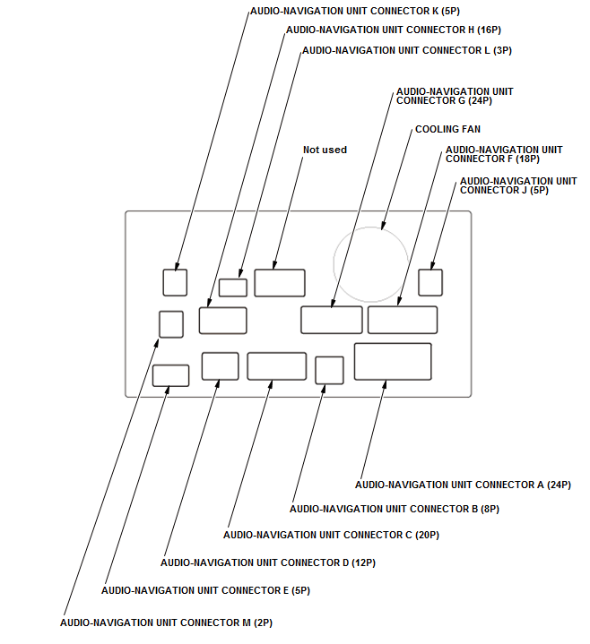
Audio-Navigation Unit Connector for Inputs and Outputs (2016-17)
Audio-Navigation Unit Connector for Inputs and Outputs
 Courtesy of HONDA, U.S.A., INC. Courtesy of HONDA, U.S.A., INC.
|
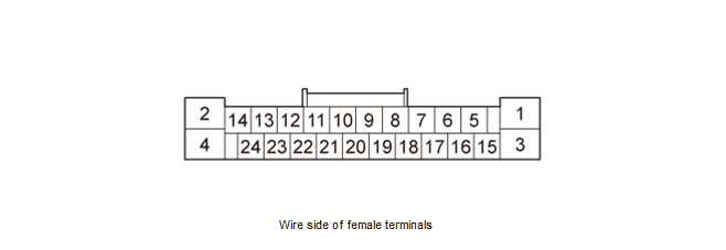
AUDIO-NAVIGATION UNIT CONNECTOR A (24P)
 Courtesy of HONDA, U.S.A., INC. Courtesy of HONDA, U.S.A., INC.
|
| Cavity |
Wire Color |
Terminal Name |
Description |
Voltage (about) |
Symptom |
| A1 |
BLK |
GND |
Ground for audio-navigation unit (G504) |
Vehicle in ACC mode: Less than 0.2 V |
If open: Center display unit screen goes black (backlight still operates). Audio system does not work.If shorted to ground: No effect on system. |
| A2 |
BLU |
B-CAN_L |
Communication signal |
- - - |
If open: System Links B-CAN icon shows red.If shorted: Same diagnostic conditions as when open, and also sets the B-CAN DTC (B-CAN BUS OFF). |
| A3 |
GRN |
+B BACK UP |
Continuous power source |
Battery voltage |
If open: Center display unit screen goes black (backlight still operates). Audio system does not work.If shorted to ground: Blows the No. A29 (10 A) fuse in the under-hood fuse/relay box. |
| A4 |
PNK |
B-CAN_H |
Communication signal |
- - - |
If open: System Links B-CAN icon shows red.If shorted: Same diagnostic conditions as when open, and also sets the B-CAN DTC (B-CAN BUS OFF). |
| A5 |
GRN |
RL PRE+ |
Outputs sound signal for left rear channel |
- - - |
- - - |
| A6 |
RED |
RL PRE - |
Outputs sound signal for left rear channel |
- - - |
- - - |
| A7 |
Not used |
Not used |
- - - |
- - - |
- - - |
| A8 |
GRY |
SH RL PRE |
Shield for terminals No. 5, No. 6, No. 9, and No. 10 |
- - - |
- - - |
| A9 |
BLK |
RR PRE + |
Outputs sound signal for right rear channel |
- - - |
- - - |
| A10 |
WHT |
RR PRE - |
Outputs sound signal for right rear channel |
- - - |
- - - |
| A11 |
BRN |
REMOTE SW GND |
Audio remote switch ground |
Vehicle in ACC mode: Less than 0.2 V |
- - - |
| A12 |
YEL |
SCTY RADIO SW2 |
Security signal from center display unit |
- - - |
If open: The security system sets. |
| A13 |
LT BLU |
K LINE |
Detects scan tool signal (serial data) |
- - - |
- - - |
| A14 |
Not used |
Not used |
- - - |
- - - |
- - - |
| A15 |
BLK |
FL PRE + |
Outputs sound signal for left channel |
- - - |
- - - |
| Cavity |
Wire Color |
Terminal Name |
Description |
Voltage (about) |
Symptom |
| A16 |
WHT |
FL PRE - |
Outputs sound signal for front channel |
- - - |
- - - |
| A17 |
Not used |
Not used |
- - - |
- - - |
- - - |
| A18 |
GRY |
SH FL PRE |
Shield for terminals No. 15, No. 16, No. 19, and No. 20 |
- - - |
- - - |
| A19 |
GRN |
FR PRE + |
Outputs sound signal for right channel |
- - - |
- - - |
| A20 |
RED |
FR PRE - |
Outputs sound signal for right channel |
- - - |
- - - |
| A21 |
YEL |
SWD +B |
Outputs audio-navigation unit on signal |
Vehicle in ACC mode: Battery voltage |
- - - |
| A22 |
PNK |
AUDIO REMOTE SW |
Detects control signal from audio remote switch |
Vehicle in ACC mode: 2.5 V - 2.9 V |
- - - |
| A23 |
Not used |
Not used |
- - - |
- - - |
- - - |
| A24 |
PUR |
ACC |
Power source for accessories |
Vehicle in ACC mode: Battery voltage |
If open: Center display unit screen goes black. Audio system does not work.If shorted to ground: Blows the No. B19 (7.5 A) fuse in the under-dash fuse/relay box. |
AUDIO-NAVIGATION UNIT CONNECTOR B (8P)
 Courtesy of HONDA, U.S.A., INC. Courtesy of HONDA, U.S.A., INC.
|
| Cavity |
Wire Color |
Terminal Name |
Description |
Voltage (about) |
Symptom |
| B1 |
PNK |
CTR PRE + |
Outputs sound signal for front center channel |
- - - |
- - - |
| B2 |
GRY |
SH CTR SUB W PRE |
Shield for terminals No. 1, No. 3, No. 5, and No. 7 |
- - - |
- - - |
| B3 |
LT GRN |
CTR PRE - |
Outputs sound signal for front center channel |
- - - |
- - - |
| B4 |
GRN |
ANC CHK2 |
Outputs ANC test signal |
Vehicle in ACC mode, ANC is ON: 5 V Vehicle in ACC mode, ANC is OFF: Less than 0.2 V |
- - - |
| B5 |
LT BLU |
SUB W PRE + |
Outputs sound signal for subwoofer channel |
- - - |
- - - |
| B6 |
Not used |
Not used |
- - - |
- - - |
- - - |
| B7 |
BRN |
SUB W PRE - |
Outputs sound signal for subwoofer channel |
- - - |
- - - |
| B8 |
Not used |
Not used |
- - - |
- - - |
- - - |
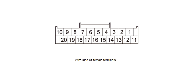
AUDIO-NAVIGATION UNIT CONNECTOR C (20P)
 Courtesy of HONDA, U.S.A., INC. Courtesy of HONDA, U.S.A., INC.
|
| Cavity |
Wire Color |
Terminal Name |
Description |
Voltage (about) |
Symptom |
| C1 |
GRY |
SH TELEM SIG |
Shield for terminals No. 2 and No. 12 |
- - - |
- - - |
| C2 |
RED |
TELEM SIG - |
Inputs HFL prompts and telephone sound signal from telematics control unit or HandsFreeLink control unit |
- - - |
- - - |
| C3 |
Not used |
Not used |
- - - |
- - - |
- - - |
| C4 |
LT BLU |
RS485 - |
Communication signal to stereo amplifier |
- - - |
If open/shorted: Stereo amplifier does not work. No sound is heard from speakers.System Links AMP icon shows red. |
| C5 |
PUR |
RS485 + |
Communication signal to stereo amplifier |
- - - |
If open/shorted: Stereo amplifier does not work. No sound is heard from speakers.System Links AMP icon shows red. |
| C6 |
YEL |
AUX GND |
Ground for auxiliary jack assembly |
- - - |
- - - |
| C7 |
GRY |
SH AUX |
Shield for terminals No. 8, No. 17, and No. 18 |
- - - |
- - - |
| C8 |
WHT |
AUX SGND |
Ground for sound signal from auxiliary jack assembly |
- - - |
- - - |
| C9 |
Not used |
Not used |
- - - |
- - - |
- - - |
| C10 |
Not used |
Not used |
- - - |
- - - |
- - - |
| C11 |
Not used |
Not used |
- - - |
- - - |
- - - |
| C12 |
GRN |
TELEM SIG + |
Inputs HFL prompts and telephone sound signal from telematics control unit or HandsFreeLink control unit |
- - - |
- - - |
| C13 |
Not used |
Not used |
- - - |
- - - |
- - - |
| C14 |
Not used |
Not used |
- - - |
- - - |
- - - |
| C15 |
GRY |
SH RS485 |
Shield for terminals No. 4 and No. 5 |
- - - |
- - - |
| C16 |
GRY |
AUX DET |
Detects connection signal for auxiliary jack assembly |
Vehicle in ACC mode:
- AUX device is not connected: 3 V
- AUX device is connected: Less than 0.2 V
|
- - - |
| C17 |
RED |
AUX R CH |
Inputs sound signal from auxiliary jack assembly |
- - - |
- - - |
| Cavity |
Wire Color |
Terminal Name |
Description |
Voltage (about) |
Symptom |
| C18 |
BLK |
AUX L CH |
Inputs sound signal from auxiliary jack assembly |
- - - |
- - - |
| C19 |
Not used |
Not used |
- - - |
- - - |
- - - |
| C20 |
Not used |
Not used |
- - - |
- - - |
- - - |
AUDIO-NAVIGATION UNIT CONNECTOR D (12P)
 Courtesy of HONDA, U.S.A., INC. Courtesy of HONDA, U.S.A., INC.
|
| Cavity |
Wire Color |
Terminal Name |
Description |
Voltage (about) |
Symptom |
| D1 |
PUR |
GA BUS - |
GA-Net bus communication signal |
- - - |
If open/shorted: GA-Net related system does not work. Center display does not dim using dash brightness control button.System Links Display icon, TCU icon, HFL icon, SXM icon, and Remote Tuner icon shows red. |
| D2 |
GRY |
SH GA BUS |
Shield for terminals No. 1 and No. 7 |
- - - |
If open/shorted to ground: No effect on system. |
| D3 |
GRN |
GA AUDIO L - |
Inputs sound signal from telematics control unit or HandsFreeLink control unit |
- - - |
- - - |
| D4 |
WHT |
GA AUDIO R - |
Inputs sound signal from telematics control unit or HandsFreeLink control unit |
- - - |
- - - |
| D5 |
GRY |
SH GA AUDIO |
Shield for terminals No. 3, No. 4, No. 9, and No. 10 |
- - - |
- - - |
| D6 |
BRN |
GA GND |
GA-Net related units ground |
- - - |
If open: GA-Net related system does not work.System Links HFL icon, SXM icon, and Remote Tuner icon shows red.If shorted to ground: No effect on system. |
| D7 |
LT BLU |
GA BUS + |
GA-Net bus communication signal |
- - - |
If open/shorted: GA-Net related system does not work. Center display does not dim using dash brightness control button.System Links Display icon, TCU icon, HFL icon, SXM icon, and Remote Tuner icon shows red. |
| Cavity |
Wire Color |
Terminal Name |
Description |
Voltage (about) |
Symptom |
| D8 |
YEL |
GA SYS ON |
Output signal for GA-Net related units switching on/off |
Vehicle in ACC mode: Less than 0.2 V Vehicle in OFF mode: 3.3 V - Battery voltage (depends on connected slave unit)
|
If open: GA-Net related system does not work.System Links HFL icon, SXM icon, and Remote Tuner icon shows red.If shorted to ground: No effect on system. |
| D9 |
BLK |
GA AUDIO L+ |
Inputs sound signal from telematics control unit or HandsFreeLink control unit |
- - - |
- - - |
| D10 |
RED |
GA AUDIO R+ |
Inputs sound signal from telematics control unit or HandsFreeLink control unit |
- - - |
- - - |
| D11 |
Not used |
Not used |
- - - |
- - - |
- - - |
| D12 |
RED |
GA +B |
Outputs power source for GA-Net related units |
Battery voltage |
If open: GA-Net related system does not work.System Links HFL icon, SXM icon, and Remote Tuner icon shows red. |
AUDIO-NAVIGATION UNIT CONNECTOR E (5P)
 Courtesy of HONDA, U.S.A., INC. Courtesy of HONDA, U.S.A., INC.
|
| Cavity |
Wire Color |
Terminal Name |
Description |
Voltage (about) |
Symptom |
| E1 |
GRY |
SH TUNER |
Shield for terminals No. 2, No. 3, No. 4, and No. 5 |
- - - |
- - - |
| E2 |
WHT |
TUNER L - |
Inputs sound signal from tuner unit |
- - - |
- - - |
| E3 |
GRN |
TUNER L + |
Inputs sound signal from tuner unit |
- - - |
- - - |
| E4 |
RED |
TUNER R - |
Inputs sound signal from tuner unit |
- - - |
- - - |
| E5 |
BLK |
TUNER R + |
Inputs sound signal from tuner unit |
- - - |
- - - |
AUDIO-NAVIGATION UNIT CONNECTOR F (18P)
 Courtesy of HONDA, U.S.A., INC. Courtesy of HONDA, U.S.A., INC.
|
| Cavity |
Wire Color |
Terminal Name |
Description |
Voltage (about) |
Symptom |
| F1 |
BLK |
GND |
Ground for audio-navigation unit (G506) |
Vehicle in ACC mode: Less than 0.2 V |
If open: Center display unit screen goes black (backlight still operates). Audio system does not work.If shorted to ground: No effect on system. |
| F2 |
Not used |
Not used |
- - - |
- - - |
- - - |
| F3 |
BLU |
+B AUDIO(ODMD) |
Continuous power source |
Battery voltage |
If open: Center display unit screen goes black (backlight still operates). Audio system does not work. The system sets the anti-theft mode. If shorted to ground: Blows the No. A6 (15 A) fuse in the under-hood fuse/relay box. |
| F4 |
Not used |
Not used |
- - - |
- - - |
- - - |
| F5 |
LT BLU |
PARKING BRAKE SW |
Parking brake on signal from parking brake switch |
Vehicle in ACC mode, parking brake applies: Less than 0.2 V Vehicle in ACC mode, parking brake releases: 3.3 V |
If open: Diagnostic screen Car Status, PARK = 0. |
| F6 |
GRY |
SH HFT-NAVI MIC |
Shield for terminals No. 13 and No. 14 |
- - - |
If open/shorted to ground: No effect on system. |
| F7 |
Not used |
Not used |
- - - |
- - - |
- - - |
| F8 |
Not used |
Not used |
- - - |
- - - |
- - - |
| F9 |
BLK |
SH JOG |
Shield for terminal No. 16 |
- - - |
If open/shorted to ground: No effect on system. |
| F10 |
RED |
VSP |
Detects vehicle speed pulse from PCM |
Vehicle in ACC mode: 5.0 V Vehicle in ON mode: Pulses (depends on vehicle speed) |
If open/shorted: No vehicle speed pulse. Diagnostic screen Car Status, VSP = 0. |
| F11 |
Not used |
Not used |
- - - |
- - - |
- - - |
| F12 |
Not used |
Not used |
- - - |
- - - |
- - - |
| F13 |
BLU |
HFT-NAVI MIC + |
Inputs Voice Recognition (VR) prompts from microphone via telematics control unit or HandsFreeLink control unit |
Vehicle in ACC mode: 8.0 V |
If open/shorted: You cannot operate voice control. System Links screen Mic icon shows red. |
| F14 |
PNK |
HFT-NAVI MIC - |
Inputs Voice Recognition (VR) prompts from microphone via telematics control unit or HandsFreeLink control unit |
- - - |
If open/shorted: You cannot operate voice control. |
| F15 |
Not used |
Not used |
- - - |
- - - |
- - - |
| F16 |
WHT |
JOG |
Inputs center switch panel and interface dial operation signal |
- - - |
If open/shorted: Center switch panel/interface dial does not work. |
| Cavity |
Wire Color |
Terminal Name |
Description |
Voltage (about) |
Symptom |
| F17 |
WHT |
F-CAN_H |
Communication signal |
- - - |
If open: System Links F-CAN icon shows red.If shorted: Same diagnostic conditions as when open, and also sets the F-CAN DTC (F-CAN BUS OFF). |
| F18 |
RED |
F-CAN_L |
Communication signal |
- - - |
If open: System Links F-CAN icon shows red.If shorted: Same diagnostic conditions as when open, and also sets the F-CAN DTC (F-CAN BUS OFF). |
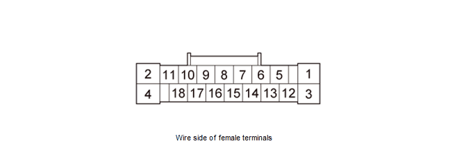
AUDIO-NAVIGATION UNIT CONNECTOR G (24P)
 Courtesy of HONDA, U.S.A., INC. Courtesy of HONDA, U.S.A., INC.
|
| Cavity |
Wire Color |
Terminal Name |
Description |
Voltage (about) |
Symptom |
| G1 |
GRY |
SH HFT SIRI |
Shield for terminals No. 13 and No. 14 |
- - - |
- - - |
| G2 |
GRY |
SH CAMERA |
Shield for terminals No. 3, No. 4, No. 15, and No. 16 |
- - - |
- - - |
| G3 |
RED |
CAMERA GND |
Ground for rearview camera |
- - - |
- - - |
| G4 |
GRN |
CAMERA GND |
Ground for video signal |
- - - |
- - - |
| G5 |
YEL |
CAMERA BIT0 |
Mode select signal for rearview camera |
0 - 7 V (depends on rearview mode) |
- - - |
| G6 |
Not used |
Not used |
- - - |
- - - |
- - - |
| G7 |
Not used |
Not used |
- - - |
- - - |
- - - |
| G8 |
Not used |
Not used |
- - - |
- - - |
- - - |
| G9 |
Not used |
Not used |
- - - |
- - - |
- - - |
| G10 |
Not used |
Not used |
- - - |
- - - |
- - - |
| G11 |
Not used |
Not used |
- - - |
- - - |
- - - |
| G12 |
Not used |
Not used |
- - - |
- - - |
- - - |
| G13 |
YEL |
HFT SIRI SIG |
Inputs voice signal for server voice recognition (reserved) |
- - - |
- - - |
| G14 |
BRN |
HFT SIRI GND |
Inputs voice signal for server voice recognition (reserved) |
- - - |
- - - |
| G15 |
WHT |
CAMERA V |
Video signal for rearview camera |
- - - |
- - - |
| G16 |
BLK |
CAMERA VCC |
Power source for rearview camera |
Vehicle in ACC mode: 8.0 V |
- - - |
| G17 |
LT BLU |
CAMERA ADPT |
Control signal for rearview camera |
Less than 0.2 V |
If open: System Links Rear Camera icon shows red. |
| G18 |
PUR |
CAMERA BIT1 |
Mode select signal for rearview camera |
0 - 7 V (depends on rearview mode) |
- - - |
| G19 |
Not used |
Not used |
- - - |
- - - |
- - - |
| Cavity |
Wire Color |
Terminal Name |
Description |
Voltage (about) |
Symptom |
| G20 |
Not used |
Not used |
- - - |
- - - |
- - - |
| G21 |
Not used |
Not used |
- - - |
- - - |
- - - |
| G22 |
Not used |
Not used |
- - - |
- - - |
- - - |
| G23 |
Not used |
Not used |
- - - |
- - - |
- - - |
| G24 |
GRY |
BACK LT |
Reverse signal of select lever from reverse relay circuit |
Vehicle in ON mode, transmission is shifted to R position/mode: Battery voltageVehicle in ON mode, transmission is shifted to any position/mode other than R position/mode: Less than 0.2 V |
If open/shorted to ground: No change to rearview camera image.Diagnostic screen Car Status, BACK = 0. |
AUDIO-NAVIGATION UNIT CONNECTOR H (16P)
 Courtesy of HONDA, U.S.A., INC. Courtesy of HONDA, U.S.A., INC.
|
| Cavity |
Wire Color |
Terminal Name |
Description |
Voltage (about) |
Symptom |
| H1 |
GRY |
SH AUX NAVI |
Shield for terminals No. 2 and No. 10 |
- - - |
- - - |
| H2 |
RED |
AUX NAVI GND |
Ground for front audio signal of voice guidance |
- - - |
- - - |
| H3 |
Not used |
Not used |
- - - |
- - - |
- - - |
| H4 |
Not used |
Not used |
- - - |
- - - |
- - - |
| H5 |
Not used |
Not used |
- - - |
- - - |
- - - |
| H6 |
Not used |
Not used |
- - - |
- - - |
- - - |
| H7 |
Not used |
Not used |
- - - |
- - - |
- - - |
| H8 |
Not used |
Not used |
- - - |
- - - |
- - - |
| H9 |
Not used |
Not used |
- - - |
- - - |
- - - |
| H10 |
GRN |
AUX NAVI |
Outputs front audio signal of voice guidance and Voice Recognition (VR) prompts |
- - - |
- - - |
| H11 |
LT GRN |
HFT MUTE |
Inputs HFL mute signal |
0 - 9.0 V (depends on HFL status) |
- - - |
| H12 |
Not used |
Not used |
- - - |
- - - |
- - - |
| H13 |
Not used |
Not used |
- - - |
- - - |
- - - |
| H14 |
Not used |
Not used |
- - - |
- - - |
- - - |
| H15 |
Not used |
Not used |
- - - |
- - - |
- - - |
| H16 |
Not used |
Not used |
- - - |
- - - |
- - - |
AUDIO-NAVIGATION UNIT CONNECTOR J (5P)
 Courtesy of HONDA, U.S.A., INC. Courtesy of HONDA, U.S.A., INC.
|
| Cavity |
Wire Color |
Terminal Name |
Description |
Voltage (about) |
Symptom |
| J1 |
- - - |
HFT USB GND |
Ground for communication signal |
- - - |
- - - |
| J2 |
- - - |
HFT USB VBUS |
Outputs power source for USB |
- - - |
- - - |
| J3 |
- - - |
HFT USB DATA + |
Communication signal for telematics control unit or HandsFreeLink control unit |
- - - |
- - - |
| J4 |
- - - |
HFT USB DATA - |
Communication signal for telematics control unit or HandsFreeLink control unit |
- - - |
- - - |
| J5 |
- - - |
HFT USB SH |
Shield for terminals No. 1, No. 2, No. 3, and No. 4 |
- - - |
- - - |
AUDIO-NAVIGATION UNIT CONNECTOR K (5P)
 Courtesy of HONDA, U.S.A., INC. Courtesy of HONDA, U.S.A., INC.
|
| Cavity |
Wire Color |
Terminal Name |
Description |
Voltage (about) |
Symptom |
| K1 |
- - - |
USB GND |
Ground for communication signal |
- - - |
If open: USB device is not recognized.System Links USB icon shows red although USB device is connected to USB port. |
| K2 |
- - - |
USB VBUS |
Outputs power source for USB device |
- - - |
If open/shorted: USB device is not recognized.System Links USB icon shows red although USB device is connected to USB port. |
| K3 |
- - - |
USB DATA + |
Communication signal |
- - - |
If open/shorted: USB device is not recognized.System Links USB icon shows red although USB device is connected to USB port. |
| Cavity |
Wire Color |
Terminal Name |
Description |
Voltage (about) |
Symptom |
| K4 |
- - - |
USB DATA - |
Communication signal |
- - - |
If open/shorted: USB device is not recognized.System Links USB icon shows red although USB device is connected to USB port. |
| K5 |
- - - |
USB SH |
Shield for terminals No. 1, No. 2, No. 3, and No. 4 |
- - - |
If open/shorted to ground: No effect on system. |
AUDIO-NAVIGATION UNIT CONNECTOR L (3P)
 Courtesy of HONDA, U.S.A., INC. Courtesy of HONDA, U.S.A., INC.
|
| Cavity |
Wire Color |
Terminal Name |
Description |
Voltage (about) |
Symptom |
| L1 |
- - - |
GVIF - |
Outputs video signal for center display unit |
- - - |
If open/shorted: Center display unit screen goes black (backlight still operates). Audio system does work. |
| L2 |
- - - |
GVIF + |
Outputs video signal for center display unit |
- - - |
If open/shorted: Center display unit screen goes black (backlight still operates). Audio system does work. |
| L3 |
- - - |
SH GVIF |
Shield for terminals No. 1 and No. 2 |
- - - |
If open/shorted to ground: No effect on system. |
AUDIO-NAVIGATION UNIT CONNECTOR M (2P)
 Courtesy of HONDA, U.S.A., INC. Courtesy of HONDA, U.S.A., INC.
|
| Cavity |
Wire Color |
Terminal Name |
Description |
Voltage (about) |
Symptom |
| M1 |
- - - |
GPS |
Inputs GPS signal |
- - - |
If open/shorted to ground: GPS icon on screen is not shown, System Links GPS Ant. icon shows red. |
| M2 |
BLK |
SH(GPS) |
Shield for terminal No. 1 |
- - - |
If open/shorted to ground: GPS icon on screen is not shown, System Links GPS Ant. icon shows red. |