Engine Control Module (ECM) X2 (LLT) Connector End View
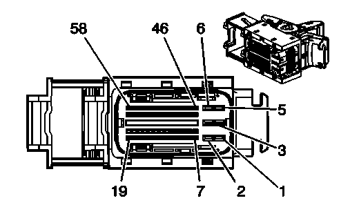 Courtesy of GENERAL MOTORS CORP.
 Engine Control Module (ECM) X2 (LLT)
| Pin |
Wire |
Circuit |
Function |
| 1 |
0.75 BK/WH |
1551 |
Ground |
| 2 |
0.75 BK/WH |
1551 |
Ground |
| 3 |
0.8 PK/BK |
5290 |
Ignition 1 Voltage |
| 4 |
0.75 BK/WH |
1551 |
Ground |
| 5 |
0.8 BK/WH |
5290 |
Ignition 1 Voltage |
| 6 |
0.8 PK/BK |
5290 |
Ignition 1 Voltage |
| 7 |
0.5 GY/WH |
3122 |
HO2S Heater Low Control - Bank 2 Sensor 1 |
| 8 |
- |
- |
Not Used |
| 9 |
0.5 TN |
2759 |
Low Reference |
| 10 |
0.5 D-GN/WH |
465 |
Fuel Pump Relay Control - Primary |
| 11 |
0.5 TN |
5514 |
Low Reference |
| 12 |
- |
- |
Not Used |
| 13 |
0.5 YE |
492 |
MAF Sensor Signal |
| 14 |
0.5 GY |
2709 |
5-Volt Reference 1 |
| 15 |
0.5 D-BU |
1161 |
APP Sensor 1 Signal |
| 16 |
- |
- |
Not Used |
| 17 |
0.5 OG/BK |
1786 |
Ignition Lock Cylinder Control Actuator Signal |
| 18 |
0.5 L-GN |
5007 |
Backup Lamp Switch Signal (MV7) |
| 19 |
0.75 WH |
1310 |
EVAP Canister Vent Solenoid Control |
| 20 |
0.5 OG/WH |
3223 |
HO2S Heater Low Control - Bank 2 Sensor 2 |
| 21 |
0.5 BN/WH |
419 |
MIL Control |
| 22 |
0.5 TN |
2760 |
Low Reference |
| 23 |
0.5 TN/WH |
3121 |
HO2S Low Signal - Bank 1 Sensor 2 |
| 24 |
0.5 TN |
3221 |
HO2S Low Signal - Bank 2 Sensor 2 |
| 25 |
0.5 L-BU |
1162 |
APP Sensor 2 Signal |
| 26 |
0.5 L-BU |
1937 |
Secondary Fuel Level Sensor Signal |
| 27 |
0.5 D-GN |
890 |
Fuel Tank Pressure Sensor Signal |
| 28-33 |
- |
- |
Not Used |
| 34 |
0.5 BN |
1271 |
Low Reference |
| 35 |
0.5 GY |
598 |
5-Volt Reference 3 |
| 36 |
0.5 D-BU |
1936 |
Primary Fuel Level Sensor Signal |
| 37 |
0.5 L-GN |
6338 |
Manual Transmission Clutch Position Sensor Signal Position (MV7) |
| 38 |
0.5 PU |
3120 |
HO2S High Signal - Bank 1 Sensor 2 |
| 39 |
0.5 OG/BK |
380 |
A/C Refrigerant Pressure Sensor Signal |
| 40 |
- |
- |
Not Used |
| 41 |
0.5 D-BU |
5985 |
Accessory Wakeup Serial Data |
| 42 |
0.5 TN/BK |
2500 |
High Speed GMLAN Serial Data Bus+ |
| 43 |
0.5 PU/WH |
821 |
VSS High Signal (MV7) |
| 44 |
0.5 D-GN/WH |
459 |
A/C Compressor Clutch Relay Control |
| 45 |
0.5 D-BU |
473 |
High Speed Cooling Fan Relay Control |
| 46 |
0.5 D-GN |
335 |
Low Speed Cooling Fan Relay Control |
| 47 |
0.5 PU |
1272 |
Low Reference |
| 48 |
0.5 TN |
1274 |
5-Volt Reference 3 |
| 49 |
0.5 WH/BK |
1164 |
5-Volt Reference 2 |
| 50 |
0.5 L-BU |
6289 |
Induction Air Temperature Sensor Signal |
| 51 |
0.5 PU |
3220 |
HO2S High Signal - Bank 2 Sensor 2 |
| 52 |
0.5 WH |
17 |
Stop Lamp Switch Signal or Stop Lamp Supply Voltage |
| 53 |
- |
- |
Not Used |
| 54 |
0.5 PK |
339 |
Ignition 1 Voltage |
| 55 |
0.5 TN |
2501 |
High Speed GMLAN Serial Data Bus- |
| 56 |
0.5 RD/WH |
340 |
Battery Positive Voltage |
| 57 |
0.5 YE |
447 |
Starter Relay Coil Control |
| 58 |
0.5 BN |
5069 |
Main Relay Control |
Connector Part Information
- Harness Type: Engine
- OEM Connector: 1928404780
- Service Connector: 88988935
- Description: 58-Way F 280 Series, Sealed (BK)
|
Terminal Part Information
- Pins: 1-6
- Terminated Lead: Pending
- Release Tool: J-38125-561
- Diagnostic Test Probe: J-35616-35 (VT)
- Terminal/Tray: 1928498058/8
- Core/Insulation Crimp: E/1
- Pins: 7, 9-11, 13-15, 17-27, 34-39, 41-52, 54-58
- Terminated Lead: 13578933
- Release Tool: J-38125-213
- Diagnostic Test Probe: J-35616-16 (L-GN)
- Terminal/Tray: 1928498135/19
- Core/Insulation Crimp: J/J
|