Removal Procedure
- Command the Discharge Start/Stop Capacitor parameter with the scan tool and discharge the multifunction energy storage capacitor. Wait 3 minutes for the capacitor to discharge.
- Disconnect the battery negative cable. Refer to Battery Negative Cable Disconnection and Connection
- Rear Compartment Side Trim Replacement - Left Side
» Remove
- {If equipped} Active Safety Control Module Bracket Bolt (1)» Remove
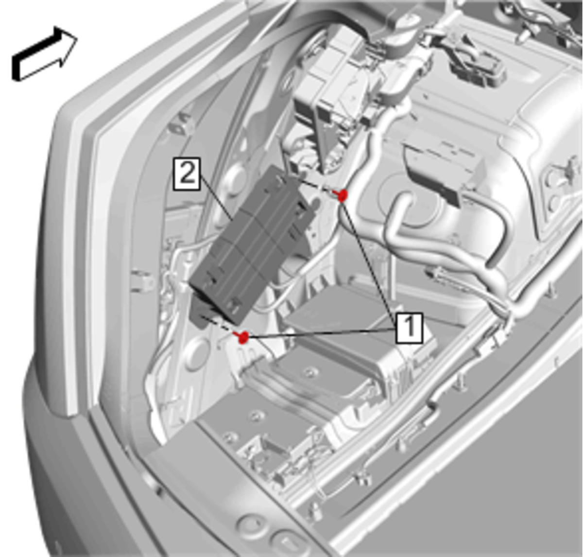 Courtesy of GENERAL MOTORS COMPANY
- {If equipped} Active Safety Control Module Bracket (2)» Reposition away
- Multifunction Energy Storage Capacitor Control Module Bracket Bolt (1)» Remove [2x]
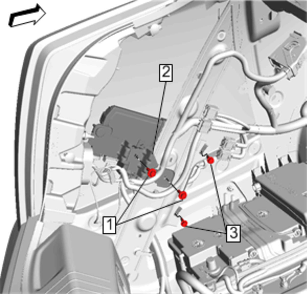 Courtesy of GENERAL MOTORS COMPANY
- Multifunction Energy Storage Capacitor Control Module Bracket Bolt (3)» Remove [2x]
- Check the voltage at K176 Stop/Start Multifunction Energy Storage Capacitor Control Module terminal X3-A to Ground, verify it is less than 1 volt.
- If greater than 1 Volt, disconnect X3-A at C10 Stop/Start Multifunction Energy Storage Capacitor Control Module and apply electrical tape on the terminal to prevent discharge.
- Auxiliary Generator Battery Jumper Cable Nut (1)» Remove [3x]
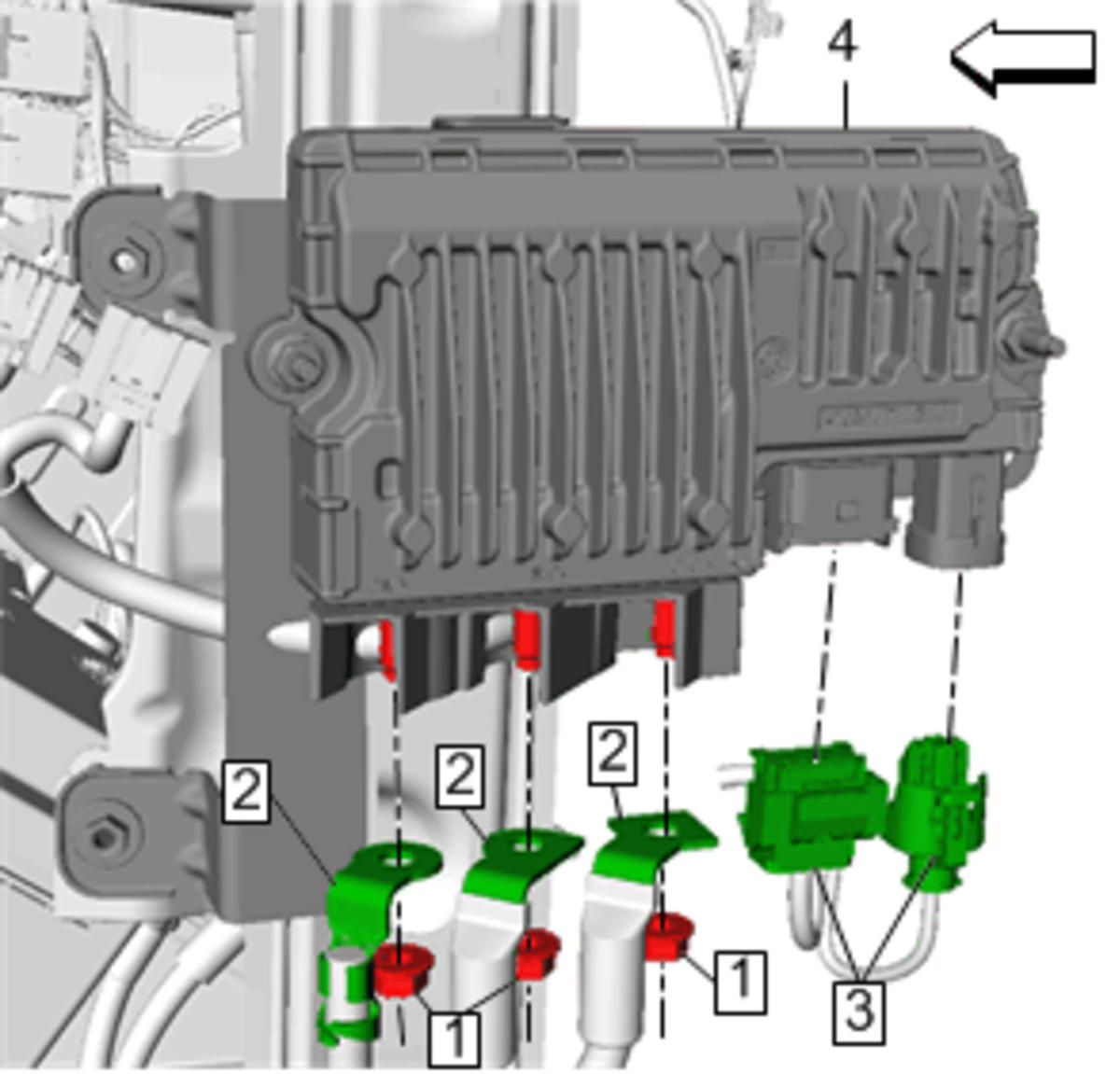 Courtesy of GENERAL MOTORS COMPANY
- Auxiliary Generator Battery Jumper Cable (2)» Remove [3x]
- Disconnect the electrical connectors (3).
- Multifunction Energy Storage Capacitor Control Module (4)» Remove
- Multifunction Energy Storage Capacitor Control Module Nut (1)» Remove [2x]
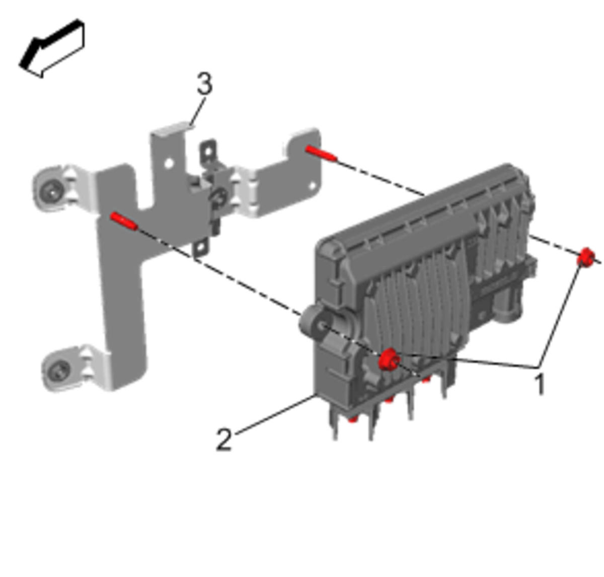 Courtesy of GENERAL MOTORS COMPANY
- Multifunction Energy Storage Capacitor Control Module Bracket (3)» Remove