Tie Rod Removal
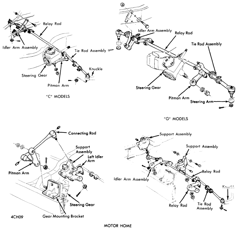
- Raise vehicle and remove tie rod fasteners. Remove outer ball stud by tapping on steering arm at tie rod end with a light hammer while using a heavy hammer as a backing. Remove inner ball stud from relay rod using same procedure.
 Courtesy of GENERAL MOTORS COMPANY
 Courtesy of GENERAL MOTORS COMPANY
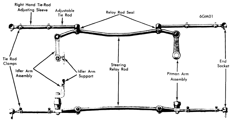
- To remove tie rod ends from tie rod, loosen clamp bolts and unscrew end assemblies. Tie rod adjuster clamp bolts often become rusted in service. It is recommended that if torque required to remove the nut from a bolt after break-away exceeds 7 ft. lbs., discard the nuts and bolts. Apply penetrating oil between clamps and tube, and rotate clamps until they move freely. Use new fasteners of same part number during reassembly to assure proper clamping at specified nut torque.
- To install tie rods, use following procedure: Lubricate tie rod threads with EP chassis lube and install tie rod ends making sure both are threaded an equal distance from tie rod. Check that threads on ball studs and nuts are clean and smooth. Check condition of ball stud seals and replace if necessary using suitable tool (J-24434). Install ball studs in steering arms and relay rod. Install ball stud nuts and torque to specifications, and install new cotter pins. Adjust toe-in. See Wheel Alignment Specifications & Procedures in WHEEL ALIGNMENT Section.
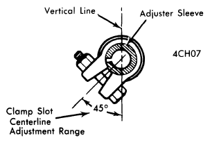
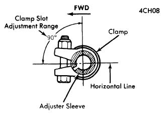
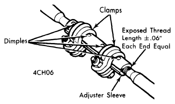
- Before tightening tie rod adjusting sleeve clamp bolts, note following: Clamps must be positioned between locating dimples at either end of sleeve as shown in illustration. Slot in adjuster sleeve must be within open area of clamp jaws or not closer than 0.10" to edge of clamp jaw opening. Rotate both inner and outer tie rod housings rearward to limit of ball joint travel before tightening clamps. Tighten clamps to specifications and return tie rod assembly to center of travel. Check each tie rod for a rotation of at least 35° using a bubble protractor and a pair of vise grips. Lubricate inner and outer tie rod ends.
 Courtesy of GENERAL MOTORS COMPANY
 Courtesy of GENERAL MOTORS COMPANY
 Courtesy of GENERAL MOTORS COMPANY