A/C Compressor Control Unit
- Locate A/C compressor control unit on top of evaporator case. Backprobe A/C compressor control unit 12-pin and 6-pin connectors. See Fig 1. Measure voltage at specified A/C compressor control unit terminals. Repair circuit(s) as required.
- Terminal No. 1 (Blue/Red wire) is A/C compressor control unit power supply. With ignition switch on, battery voltage should be present.
- Terminal No. 8 (Black wire) is A/C compressor control unit ground. There should be zero volts at all times.
- Terminal No. 2 (Red/Yellow wire) is A/C compressor control unit power supply when A/C switch is in ECONO mode. With ignition and blower switches on, and A/C switch to first level, battery voltage should be present.
- Terminal No. 7 (Blue/Black wire) is A/C compressor control unit power supply when A/C switch is in DRY mode. With ignition and blower switches on, and A/C switch to second level, battery voltage should be present.
- Terminal No. 6 (Green wire) becomes power supply for A/C compressor clutch relay. When compressor on conditions are satisfied, battery voltage should be present.
- Terminal No. 22 (Yellow/White wire) is air thermo sensor power supply. With ignition, blower and A/C switches are on, approximately 3 volts should be present.
- Terminal No. 26 (Yellow/Red wire) is air thermo sensor signal. There should be zero volts at all times.
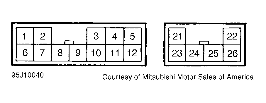 Courtesy of MITSUBISHI MOTOR SALES OF AMERICA.