Movable Steering Columns: Disassembly: Notes
- Disconnect battery, disconnect steering shaft at flex coupling and remove steering wheel trim pad, steering wheel, and the turn signal lever. The wheel should be in the full up position. Disconnect quick coupler for turn signal wiring at lower end of column. Remove two screws on turn signal switch.
- Remove wire harness retainer screw and clip on upper column outer tube and lift switch over the steering column shaft.
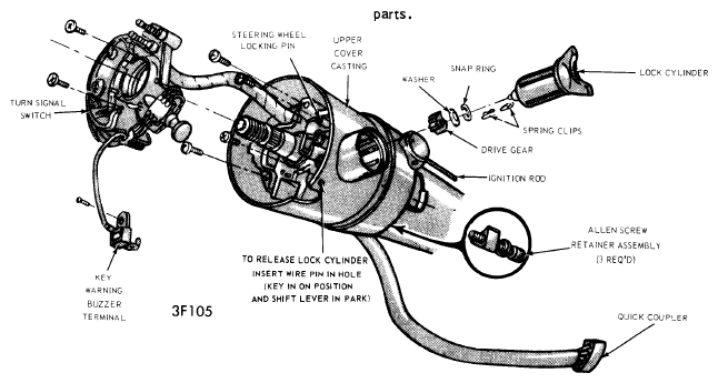
- Place gear shift selector in "P" position and insert a wire pin in the ignition lock hole (hole is located between lock cylinder housing and the warning flasher button on cover casting). Turn ignition switch to "ON", depress wire pin, and lift out lock cylinder. Remove lock cylinder spring clips inside lock cylinder housing.
- Insert flat blade screwdriver into recess in drive gear at bottom of lock cylinder housing. Turn drive gear three notches in counterclockwise direction. Remove snap ring, washer, and drive gear. Note position of drive gear to upper actuator teeth for reinstallation.
- Remove phillips screws on cover casting and lift casting off of assembly. The upper actuator may also be removed at this point. Remove selector dial ring (if applicable). Remove upper column trim shroud or shrouds, steering column brackets to brake support bracket, and allow column to drop down. This will expose the ignition switch.
 Courtesy of FORD MOTOR CO.
 Courtesy of FORD MOTOR CO.
- Remove three alien screws holding lower flange casting to outer tube (screws located under socket casting on outer tube). Discard screws. Remove ignition switch rod connection at switch (if necessary, start flange assembly out of column to provide free play in rod).
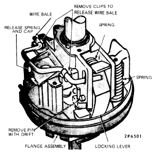
- Free wire bale which acts as a release lever for locking lever by taking out two spring clips, remove the bale. Using a small drift, drive out pin holding locking lever, remove locking lever and spring. Remove steering shaft snap ring.
- Remove two pivot pins located in side of casting assembly (use Tool T65P-3D739-A or Tools T70P-3D739-A & T67P-3D739-A), then separate upper and lower flange castings. Remove lower actuator with ignition switch rod attached. Rotate inner tube and socket casting to expose casting retaining bolt, remove this bolt and lift casting off shift tube.