Multiple Switch
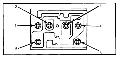
- Remove switch from vehicle. Using an ohmmeter or test light, clip a test probe on pin No. 6, which is grounded. See Fig. 1.
Place both switches in neutral position and test for continuity between pin No. 6 and pins No. 1 through 4.
 Courtesy of FORD MOTOR CO.
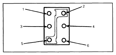
- Push both switches upward. Both No. 1 and No. 3 should lose continuity to pin No. 6. Push switches downward. No. 2 and No. 4 should lose continuity to pin No. 6.
- Remove test probe from No. 6, and connect it to feed pin (No. 5). With both switches in neutral position, no continuity should exist at remaining terminals.
- Push switches upward. No. 2 and No. 4 should show continuity with No. 5. If any switch does not test as indicated, replace complete switch assembly.
 Courtesy of FORD MOTOR CO.