Test 3 - Dis Module, Harness & Sensor
- Proceed as indicated from step 4) of TEST 2 under TESTING in this article. Remove DIS from DIS input tee. Crank engine in very short burst. If voltage reading is as specified from step 4) of TEST 2, replace DIS module. If not, reconnect module and go to next step.
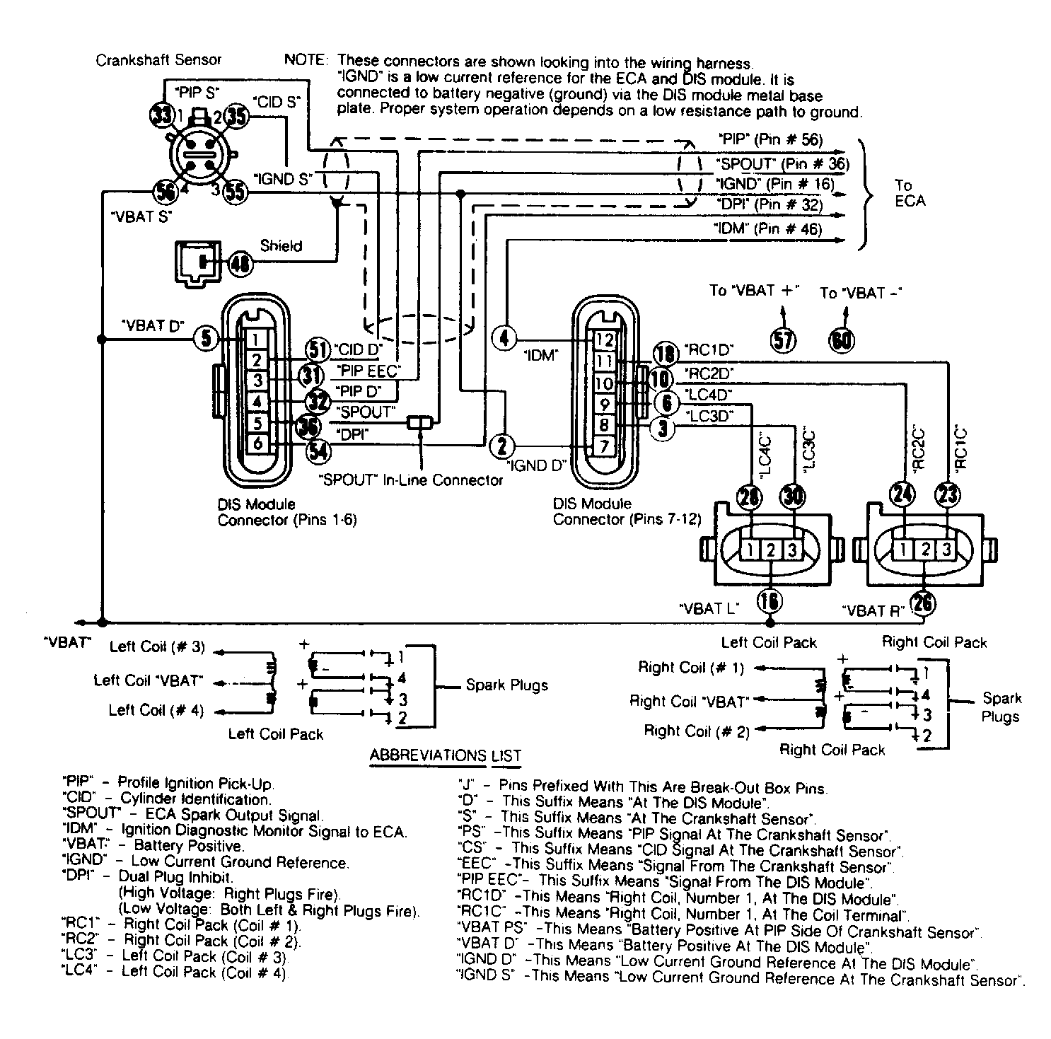
- Connect voltmeter between test pins J33 (CIDS) and J2 (IGNDD). With engine cranking, voltmeter should read zero and battery voltage. With engine running, voltmeter should read 5.5-7.5 volts. If it does, CID circuit is open. If not, go to step 3).
- Turn ignition on. Measure voltage between test pins J53 (VBATS) and J2 (IGNDD). Voltage should be between 11-14 volts. If okay, go to step 4). If not, check or repair VBATS wiring harness.
- Check resistance between test pins J51 (IGNDS) and J2 (IGNDD). If resistance is less than 5 ohms, go to step 5). If not, IGNDS circuit is open. Repair wiring harness.
- Turn ignition off. Check resistance between J51 (CIDD) and J33 (CIDS). If resistance is less than 5 ohms, go to step 6). If not, CID circuit is open. Repair wiring harness.
- With ignition off, disconnect sensor from sensor tee. Measure resistance between test pin J51 (CIDD) and J2 (IGNDD). If resistance is more than 10,000 ohms, go to step 7). If not, CID is shorted to ground. Repair wiring harness.
- Measure resistance between J51 (CIDD) and J5 (VBATD) (ignition off). If resistance is more than 10,000 ohms, replace sensor. If not, CID is shorted. Repair wiring harness.
- Measure voltage between test pins J35 (PIPS) and J2 (IGNDD). Crank engine in very short bursts. If voltage reading is zero and battery voltage while cranking engine, PIP circuit is open. Repair harness. If not, go to step 9).
- Turn ignition off. Measure resistance between J35 (PIPS) and J32 (PIPD). If resistance is less than 5 ohms, got to step 10). If not, PIP circuit is open. Repair as necessary.
- Remove DIS module from DIS input tee. Repeat step 8). If voltage is okay now, replace DIS module. If not, reconnect module and go to step 11).
- Turn ignition key on. Measure voltage between test pins J53 (VBATS) and J2 (IGNDD). If voltage is between 11-14 volts, go to step 13). If not, go to step 12).
- Disconnect sensor from tee. Repeat step 11). If okay now, replace sensor. If not, check or repair VBATS circuit.
- With ignition off, check resistance between J55 (IGNDS) and battery negative terminal. If resistance is less than 5 ohms, go to step 14). If resistance is more than 5 ohms, IGNDS circuit is open. Repair wiring harness as necessary.
- Disconnect module from module tee and sensor from sensor tee. With ignition off, measure resistance between test pins J35 (PIPS) and J5 (VBAT). If resistance is more than 10,000 ohms, go to step 15). If not, PIP is shorted to VBAT. Repair as necessary.
- With ignition off, measure resistance between J35 (PIPS) and J2 (IGNDD). If resistance is more than 10,000 ohms, replace sensor. If not, PIPS is shorted to GND. Repair as necessary.
- If from QUICK TEST, service codes 18, 28, 48 or 88 are present, replace DIS module. Repeat appropriate QUICK TEST in COMPUTERIZED ENGINE CONTROLS section. If codes are still present, replace EEC-IV computer. If no codes exists, go to appropriate QUICK TEST in COMPUTERIZED ENGINE CONTROLS section.
 Courtesy of FORD MOTOR CO.