Test B: Driver's Door Module (DDM) Does Not Respond To NGS Tester
- Turn ignition off. Disconnect DDM 12-pin connector C518 located inside of driver's door. Inspect connector for loose, damaged or corroded terminals. Pay close attention to terminal No. 1 (Light Blue/White wire). Repair connector as necessary and retest system for normal operation. If connector is okay, go to next step.
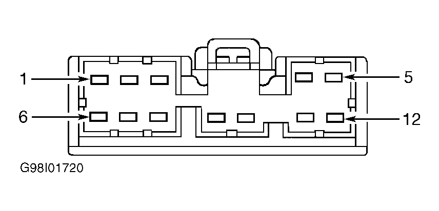
- Measure resistance of Light Blue/White wire between terminal No. 1 at connector C518 and terminal No. 7 at DLC. See Figure
and Fig 1
. If resistance is less than 5 ohms, replace DDM and retest system for normal operation. If resistance is 5 ohms or more, go to next step.
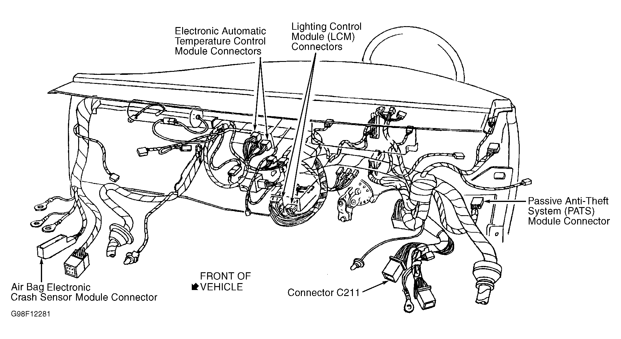
- Disconnect 16-pin connector C211 located behind left kick panel. See Fig 2
. Inspect connector for loose, damaged or corroded terminals. Repair connector as necessary and retest system for normal operation. If connector is okay, measure resistance of Light Blue/White wire between terminal No. 4 at male half of connector C211 and terminal No. 7 at DLC. See Figure
and Figure
. If resistance is less than 5 ohms, repair Light Blue/White wire between connector C211 and DDM connector. Retest system for normal operation. If resistance is 5 ohms or more, repair open Light Blue/White wire between connector C211 and DLC. Retest system for normal operation.
 Courtesy of FORD MOTOR CO.
 Courtesy of FORD MOTOR CO.