Test A: No Communication With Driver Door Module
- Turn ignition switch to LOCK position. Disconnect 4-pin Driver Door Module (DDM) harness connector C520. DDM is located in driver's door. Turn ignition switch to ON position. Measure voltage between ground and DDM harness connector C520 terminals No. 4 (Black/White wire) and No. 3 (Yellow/Light Green wire). If more than 10 volts exists at both terminals, go to next step. If 10 volts or less exists at either terminal, repair appropriate power distribution circuit. See POWER DISTRIBUTION article in WIRING DIAGRAMS.
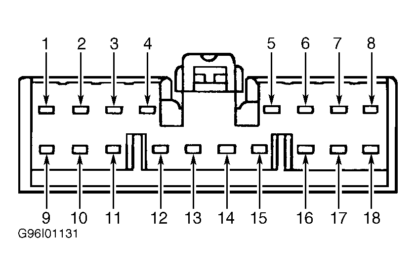
- Turn ignition switch to LOCK position. Disconnect 18-pin DDM harness connector C519. Measure resistance between ground and DDM harness connector C519 terminals No. 4 (Pink/Orange wire) and No. 15 (Black wire). See Fig 1
. If resistance is 5 ohms or greater at either terminal, repair open on Pink/Orange wire or Black wire. See WIRING DIAGRAMS
. If resistance is less than 5 ohms, repair module communications problem. See MODULE COMMUNICATIONS NETWORK - CROWN VICTORIA & GRAND MARQUIS article.
 Courtesy of FORD MOTOR CO.