Pinpoint Test A: No Communication With The Generic Electronic Module (Gem)
- A1 CHECK THE GEM POWER CIRCUITS FOR VOLTAGE
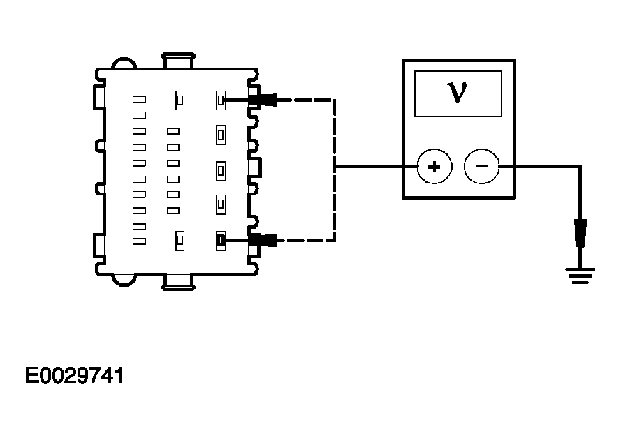
- Key in OFF position.
- Disconnect: GEM C201c.
- Key in ON position.
- Measure the voltage between the GEM C201c pin 5, circuit 29-DK20 (OG/GN), harness side and ground; and between the GEM C201c pin 1, circuit 29-AA17 (OG/WH), harness side and ground.
 Courtesy of FORD MOTOR CO.
- Are the voltages greater than 10 volts?
- Yes
: GO to A2.
- No
: REPAIR the circuit in question. CLEAR the DTCs. REPEAT the self-test. CARRY OUT the data link diagnostics test.
- A2 CHECK THE GEM GROUND CIRCUIT 31-DK20 (BK) FOR AN OPEN
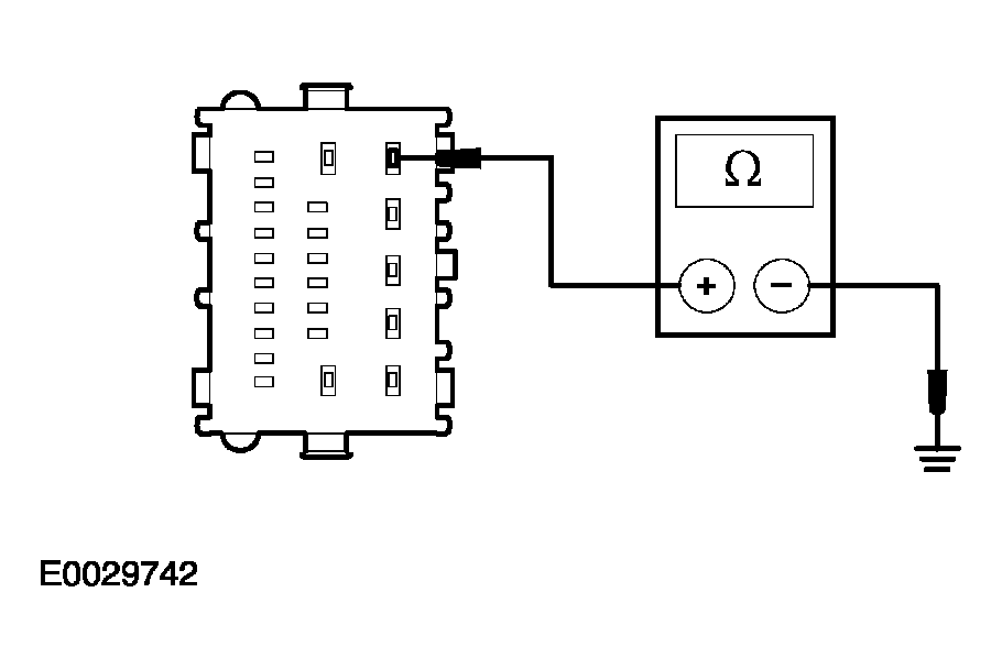
- Key in OFF position.
- Disconnect: GEM C201a.
- Measure the resistance between the GEM C201a pin 5, circuit 31-DK20 (BK), harness side and ground.
 Courtesy of FORD MOTOR CO.
- Is the resistance less than 5 ohms?
- Yes
: GO to A3.
- No
: REPAIR the circuit. CLEAR the DTCs. REPEAT the self-test. CARRY OUT the data link diagnostics test.
- A3 CHECK THE GEM GROUND CIRCUIT 91-DK20 (BK/RD) FOR AN OPEN
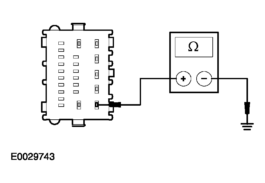
- Disconnect: GEM C201d.
- Measure the resistance between the GEM C201d pin 1, circuit 91-DK20 (BK/RD), harness side and ground.
 Courtesy of FORD MOTOR CO.
- Is the resistance less than 5 ohms?
- Yes
: REFER to MODULE COMMUNICATIONS NETWORK
to continue communication diagnosis.
- No
: REPAIR the circuit. CLEAR the DTCs. REPEAT the self-test. CARRY OUT the data link diagnostics test.