Pinpoint Test F: The Speed Control Switch Is Inoperative
- F1 CHECK THE SPEED CONTROL SWITCH
- Key in OFF position.
- Disconnect: Speed Control Actuator C122.
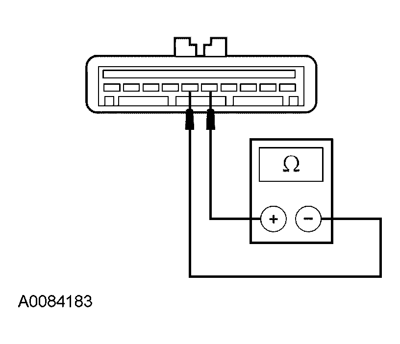
- Measure the resistance between the speed control actuator C122-5, circuit 151 (LB/BK), harness side and the speed control actuator C122-6, circuit 848 (DG/OG), harness side while pressing the switch as follows:
RESISTANCE CHECK
| Speed Control Switch |
Resistance Value |
| SET- |
108 - 132 ohms |
| SET+ |
646 - 714 ohms |
| RES |
1,980 - 2,420 ohms |
| OFF |
Less than 5 ohms |
 Courtesy of FORD MOTOR CO.
- Are the speed control switch resistance values OK?
- Yes
: GO to F6.
- No
: GO to F2
.
- F2 CHECK THE SPEED CONTROL SWITCH OPERATION
- Deactivate the air bag system. Refer to SUPPLEMENTAL RESTRAINT SYSTEM
.
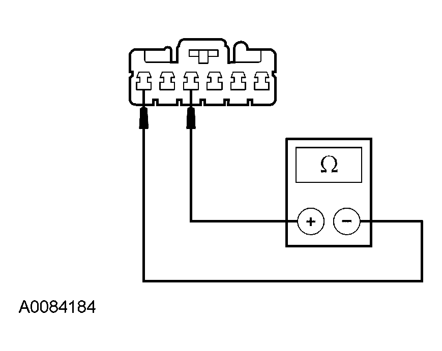
- Disconnect: Horn Switch Wiring Harness.
- Measure the resistance between the horn switch wiring harness pin 1, circuit 151 (LB/BK), harness side and the horn switch wiring harness pin 3, circuit 848 (DG/OG), harness side while pressing the switch as follows:
RESISTANCE CHECK
| Speed Control Switch |
Resistance Value |
| SET- |
108 - 132 ohms |
| SET+ |
646 - 714 ohms |
| RES |
1,980 - 2,420 ohms |
| OFF |
Less than 5 ohms |
 Courtesy of FORD MOTOR CO.
- Are the speed control switch resistance values OK?
- Yes
: GO to F4.
- No
: GO to F3
.
- F3 CHECK THE HORN SWITCH WIRING HARNESS
- Inspect the horn switch wiring harness for shorts, opens, or any damage.
- Is the horn switch wiring harness OK?
- F4 CHECK CIRCUIT 151 (LB/BK) FOR AN OPEN
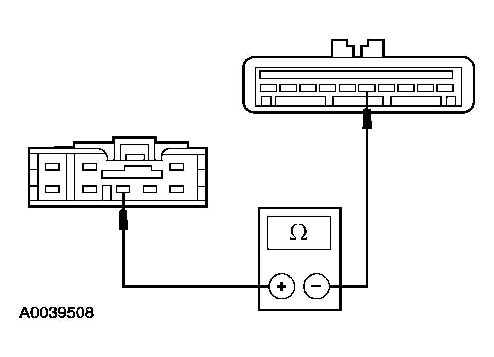
- Disconnect: Clockspring C218b.
- Measure the resistance between the clockspring C218b-6, circuit 151 (LB/BK), harness side and the speed control actuator C122-5, circuit 151 (LB/BK), harness side.
 Courtesy of FORD MOTOR CO.
- Is the resistance less than 5 ohms?
- Yes
: GO to F5
.
- No
: REPAIR the circuit. ACTIVATE the air bag system. REFER to SUPPLEMENTAL RESTRAINT SYSTEM
. TEST the system for normal operation.
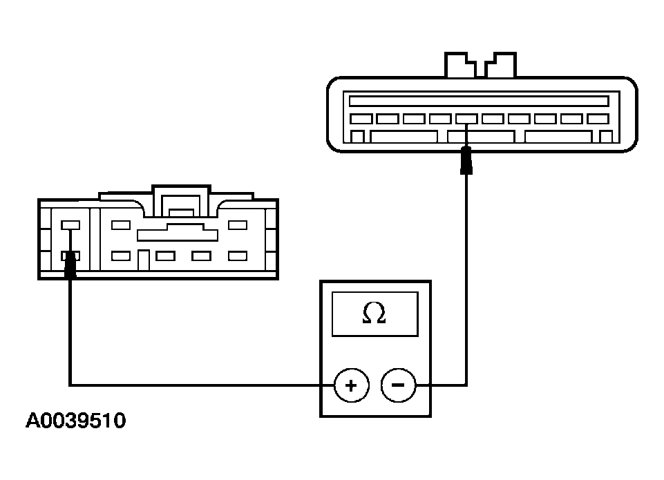
- F5 CHECK CIRCUIT 848 (DG/OG) FOR AN OPEN
- Measure the resistance between the clockspring C218b-3, circuit 848 (DG/OG), harness side and the speed control actuator C122-6, circuit 848 (DG/OG), harness side.
 Courtesy of FORD MOTOR CO.
- Is the resistance less than 5 ohms?
- F6 CHECK FOR CORRECT SPEED CONTROL ACTUATOR OPERATION
- Disconnect the speed control actuator connector.
- Check for:
- corrosion
- pushed-out pins
- Connect the speed control actuator connector and make sure it seats correctly.
- Operate the system and verify the concern is still present.
- Is the concern still present?
- Yes
: INSTALL a new speed control actuator. REFER to SPEED CONTROL ACTUATOR . TEST the system for normal operation.
- No
: The system is operating correctly at this time. The concern may have been caused by a loose or corroded connector.