Pinpoint Test C: The Transmission Control Switch Is Inoperative
- C1 CHECK THE CIRCUIT FOR VOLTAGE
- Key in OFF position.
- Disconnect: Brake Shift Interlock Module
- Key in ON position.
 Courtesy of FORD MOTOR CO.
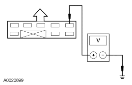
- Measure the voltage between brake shift interlock module pin 4, harness side and ground.
- Is the voltage greater than 10 volts?
- YES
: Go to C2.
- NO
: REPAIR the circuit. TEST the system for normal operation.
- C2 CHECK THE TRANSMISSION CONTROL SWITCH
 Courtesy of FORD MOTOR CO.
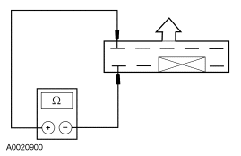
- While cycling the transmission control switch, measure the resistance between brake shift interlock module pin 4 and pin 1, component side.
- Does the resistance change from greater than 10,000 ohms to less than 5 ohms?
- YES
: Go to C3.
- NO
: INSTALL a new brake shift interlock module. TEST the system for normal operation.
- C3 CHECK THE CIRCUIT FOR AN OPEN
- Key in OFF position.
- Disconnect: Powertrain Control Module (PCM)
- Measure the resistance between brake shift interlock module pin 1 and the PCM connector pin C29.
- Is the resistance less than 5 ohms?
- YES
: Go to C4.
- NO
: REPAIR the circuit. TEST the system for normal operation.
- C4 CHECK THE CIRCUIT FOR A SHORT TO GROUND
- Measure the resistance between PCM connector pin C29 and chassis ground.
- Is the resistance greater than 10,000 ohms.
- YES
: Go to C5.
- NO
: REPAIR the circuit. TEST the system for normal operation.
- C5 CHECK THE CIRCUIT FOR A SHORT TO VOLTAGE
- Measure the voltage between PCM connector pin C29 and chassis ground.
- Is voltage present?
- YES
: REPAIR the circuit. TEST the system for normal operation.
- NO
: REFER to the INTRODUCTION - GASOLINE ENGINES
article.