Pinpoint Test B: The Tilt Adjustment is Inoperative - Using the Memory Set Switch/Using the Remote Transmitter/Using the Easy E
Steering Column
Pinpoint Tests
Pinpoint Test B: The Tilt Adjustment is Inoperative - Using the Memory Set Switch/Using the Remote Transmitter/Using the Easy Entry/Exit Feature
Refer to Wiring Diagram Set 128, Adjustable Steering Column for schematic and connector information. Diagrams By Number
NOTE: The Hall-effect sensor return circuit will change from VPP08 (WH) at the adjustable pedal motor to RPP08 (GN) at the Driver Seat Module (DSM) as it passes through in-line connector C300.
Normal Operation
To move the power tilt column to position 1, the memory SET switch provides a voltage signal to the Driver Seat Module (DSM) through circuit CPS15 (VT/WH). The DSM then sends voltage to the power tilt motor through circuits CPP03 (GN/VT) and CPP22 (GY/BN) depending on the current column position. To move the power tilt column to position 2, the memory SET switch provides a voltage signal to the DSM through circuit CPS16 (YE).
The DSM sends voltage to the power tilt motor through circuits CPP03 (GN/VT) and CPP22 (GY/BN) depending on the current column position. The DSM uses a Hall-effect position sensor, attached to the column motor assembly, to identify the current column position. The DSM sends a reference voltage along circuit VPP17 (VT/BN), through the Hall-effect position sensor and back to the DSM along the signal return circuit, RPP06 (GN)/VPP08 (WH).
The power tilt motor and Hall-effect position sensor assembly are not serviceable, if a new assembly is needed then a new steering column must be installed.
This pinpoint test is intended to diagnose the following:
- Wiring, terminals or connectors
- Memory SET switch
- Remote transmitter
- Power tilt motor
- DSM
PINPOINT TEST B: THE TILT ADJUSTMENT IS INOPERATIVE - USING THE MEMORY SET SWITCH/USING THE REMOTE TRANSMITTER/USING THE EASY ENTRY/EXIT FEATURE
NOTICE: Use the Flex Probe Kit for all test connections to prevent damage to the wiring terminals. Do not use standard multi-meter probes.
-------------------------------------------------
B1 CHECK THE OPERATION OF THE DRIVER SEAT AND THE EXTERIOR MIRRORS USING THE MEMORY SET SWITCH
- Observe the exterior mirrors and driver seat while recalling the memory positions using the memory SET switch.
- Do the memory seats and mirrors move to the memory position selected?
Yes
If only the adjustable column is inoperative, GO to B2.
No
If the memory seats and mirrors are also inoperative, REFER to Seats.
-------------------------------------------------
B2 CHECK THE OPERATION OF THE DRIVER SEAT USING THE EASY ENTRY/EXIT FEATURE
- NOTE: Verify that the easy entry/exit feature is selected ON using the message center.
- Observe the driver seat while using the easy entry/exit feature.
- Does the driver seat move to the easy entry/exit positions?
Yes
GO to B3.
No
REFER to Seats.
-------------------------------------------------
B3 CHECK THE DSM POWER TILT (TILT_UPDWN) ACTIVE COMMAND
- Connect the scan tool.
- Ignition ON.
- Enter the following diagnostic mode on the scan tool: DataLogger - DSM.
- NOTE: When commanded, the DSM will move the steering column a maximum of one second.
- While observing the steering column, toggle the TILT_UP and TILT_DN active commands UP then DOWN.
- Does the steering column move in the appropriate direction when commanded?
Yes
The system is operating correctly at this time. Concern may have been caused by a loose connector. CHECK the power tilt motor connector, the power tilt switch connector and the DSM connectors for looseness. CLEAR the DTCs. REPEAT the self-test.
No
GO to B4.
-------------------------------------------------
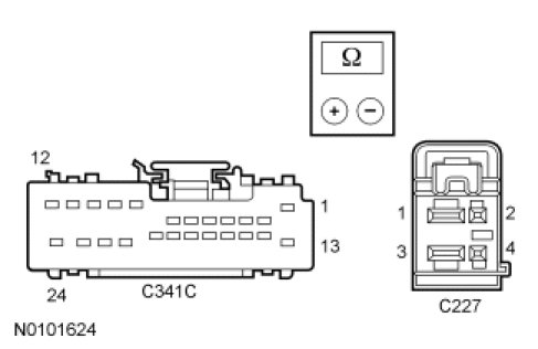
B4 CHECK THE POWER TILT MOTOR CIRCUITS FOR AN OPEN
- Ignition OFF.
- Disconnect: DSM C341C.
- Disconnect: Power Tilt Motor C227.
- Measure the resistance between DSM C341C, harness side and the power tilt motor C227, harness side as indicated in the following chart:
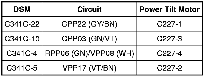
- Are the resistances less than 5 ohms?
Yes
GO to B5.
No
REPAIR the affected circuit(s). CLEAR the DTCs. REPEAT the self-test.
-------------------------------------------------
B5 CHECK THE POWER TILT MOTOR CIRCUITS FOR A SHORT TO GROUND
- Measure the resistance between ground and:
- DSM C341C-4, circuit RPP06 (GN)/VPP08 (WH), harness side.
- DSM C341C-5, circuit VPP17 (VT/BN), harness side.
- DSM C341C-10, circuit CPP03 (GN/VT), harness side.
- DSM C341C-22, circuit CPP22 (GY/BN), harness side.
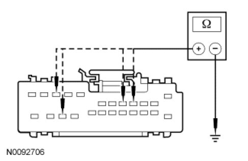
- Are the resistances greater than 10,000 ohms?
Yes
GO to B6.
No
REPAIR the affected circuit(s). CLEAR the DTCs. REPEAT the self-test.
-------------------------------------------------
B6 CHECK THE POWER TILT MOTOR CIRCUITS FOR A SHORT TO VOLTAGE
- Ignition ON.
- Measure the voltage between ground and:
- DSM C341C-4, circuit RPP06 (GN)/VPP08 (WH), harness side.
- DSM C341C-5, circuit VPP17 (VT/BN), harness side.
- DSM C341C-10, circuit CPP03 (GN/VT), harness side.
- DSM C341C-22, circuit CPP22 (GY/BN), harness side.

- Is any voltage present?
Yes
REPAIR the affected circuit(s). CLEAR the DTCs. REPEAT the self-test.
No
GO to B7.
-------------------------------------------------
B7 CHECK THE POWER TILT MOTOR OPERATION
- Ignition OFF.
- Connect a fused jumper wire between power tilt motor C227-1, component side and the battery positive terminal. Momentarily connect a jumper wire between power tilt motor C227-3, component side, and the battery negative terminal.
- Connect a fused jumper wire between power tilt motor C227-3, component side and the battery positive terminal. Momentarily connect a jumper wire between power tilt motor C227-1, component side, and the battery negative terminal.
- Does the power tilt motor operate first in one direction and then in the opposite direction?
Yes
GO to B8.
No
INSTALL a new power tilt motor. REFER to Steering Column Motor Service and Repair. CLEAR the DTCs. REPEAT the self-test.
-------------------------------------------------
B8 CHECK THE DSM CONNECTOR
- Check DSM C341C for:
- corrosion.
- pushed-out pins.
- spread terminals.
- Connect: DSM C341C.
- Connect: Power Tilt Motor C227.
- Make sure the connectors are seated correctly, then operate the system and verify the concern is still present.
- Is the concern still present?
Yes
INSTALL a new DSM. REFER to Body Control Systems. CLEAR the DTCs. REPEAT the self-test.
No
The system is operating correctly at this time. Concern may have been caused by a loose or corroded connector.
-------------------------------------------------