Normal Operation
WARNING: This page is about a different car, the 2017 Ford F-150. However, it is still accessible from the selected car via links, so may be relevant.
The PSCM wiring harness circuit provides 5 connections and 2 fuses: (1) threaded ground joint, (2) high-current BJB joint or connector, (3) in-line HS-CAN ignition signal connector, (4) power and ground connector at the PSCM, (5) HS-CAN ignition signal connector at the PSCM, (6) high-current BJB PSCM MEGA fuse, and (7) BJB ignition fuse. Specific circuit schematics are provided in Power Steering Controls
. The ignition portion of the circuit is responsible for waking up the PSCM.
Concerns with the PSCM wiring harness or fuses may result in a loss of communication between the PSCM and other modules which may result in reduced steering assist. The purpose of the PSCM Wire Harness Circuit Integrity Test is to assist with the identification of the root cause of the following wiring circuit concerns:
- Other modules losing communication with the PSCM or the PSCM does not respond to the diagnostic scan tool - concerns with any of the PSCM 5 wiring harness connections or wires, 2 fuses or the charging system can trigger U0131 DTCs in other modules.
- PSCM losing communication with other modules - any concerns with the PSCM in-line electrical connectors, wiring or the PSCM B electrical connector or wiring can trigger DTC U0001, U0100, U0121, U0122, U0126, U0140, U0151, U0155, U0159, U019B or U023A. Any concerns with the other module can also result in the PSCM losing communication with another module.
- The PSCM voltage supply concerns - any concerns with the MEGA fuse, charging system, power & ground connections or wiring trigger DTC B1304 or U3003.
- Intermittent loss of assist - any attached connection or connector, wire, or fuse not firmly and tightly connected or seated can trigger an intermittent loss of assist.
If any of the DTCs listed in the table below are present, diagnose them before continuing with this pinpoint test.
STEERING GEAR MOUNTED EPAS - PSCM DTCS
| DTC |
Description |
| C102D |
High Friction Inside Power Steering |
| C1B00 |
Steering Angle Sensor |
| C200B |
Steering Shaft Torque Sensor 1 |
| C200C |
Steering Shaft Torque Sensor 2 |
| C200D |
Motor Rotation Angle Sensor |
| P061A |
Internal Control Module Torque Performance |
| P160C |
Control Module Software Performance |
| U0300 |
Internal Control Module Software Incompatibility |
| U2011 |
Motor |
| U2100 |
Initial Configuration Not Complete |
| U3000 |
Control Module |
NOTE:
Use the correct probe adapter(s) when making measurements. Failure to use the correct probe adapter(s) may cause damage to the connector.
NOTE:
Failure to disconnect the battery when instructed results in false resistance readings.
 Courtesy of FORD MOTOR CO.
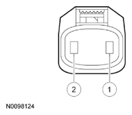
 CONNECTOR PIN REFERENCE (HARNESS SIDE)
| Circuit |
Pin |
| GND (Ground) - GD108 |
1 (BLACK/VIOLET) |
| B+ (Battery Positive Voltage) - SBF04 |
2 (GREEN/RED) |
 Courtesy of FORD MOTOR CO.
 CONNECTOR PIN REFERENCE (HARNESS SIDE)
| Circuit |
Pin |
| CAN- (Controller Area Network) - VDB26 |
3 (GRAY/BLUE) |
| CAN+ (Controller Area Network) - VDB25 |
2 (GREEN/ORANGE) |
| IGN START/RUN (Ignition START/RUN) - CBBA5 |
1 (WHITE/ORANGE) |
 Courtesy of FORD MOTOR CO.
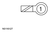
 CONNECTOR PIN REFERENCE (HARNESS SIDE)
| Circuit |
Pin |
| B+ (Battery Positive Voltage) - SBF04 |
1 (GREEN/RED) |
 Courtesy of FORD MOTOR CO.
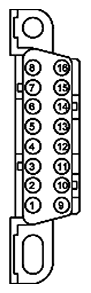
 CONNECTOR PIN REFERENCE (HARNESS SIDE)
| Circuit |
Pin |
| CAN- (Controller Area Network) - VDB26 |
11 (GRAY/BLUE) |
| CAN+ (Controller Area Network) - VDB25 |
3 (GREEN/ORANGE) |
- A1: CHECK PSCM COMMUNICATION WITH THE DIAGNOSTIC SCAN TOOL
- Ignition ON, engine running.
- Carry out the PSCM self-test.
- Does the diagnostic scan tool communicate with the PSCM and retrieve DTCs?
| Yes |
No |
| GO to A2. |
If diagnostics in Module Communications Network
have not yet been carried out, DIAGNOSE the PSCM cannot communicate with the diagnostic scan tool. REFER to Diagnosis and Testing in Module Communications Network
.
If diagnostics in Module Communications Network
were carried out prior to following this test, GO to A4. |
- A2: CHECK PSCM DTCS
NOTE:
The PSCM reporting only DTC U3003:68 does not indicate a concern with the EPAS system.
- Review the DTCs retrieved in the previous step.
- Is DTC B1304:68, U0001 or U3003 present or are any Lost Communication DTCs present?
| Yes |
No |
For other modules lost communication with the PSCM (U0131) or PSCM DTC B1304, U0001 or U3003, GO to A4.
For all PSCM lost communication with other modules DTCs, GO to A3. |
If no DTCs are present in the PSCM, GO to A4.
If other PSCM DTCs are present with the lost communication concern or PSCM DTC B1304, U0001 or U3003,
DIAGNOSE all other PSCM DTCs before continuing with this pinpoint test. GO to the PSCM DTC Index . |
- A3: CHECK COMMUNICATION WITH OTHER MODULES
- Ignition ON, engine running.
- Using a diagnostic scan tool, carry out the self test for the non-communicating module.
- Does the module communicate with the diagnostic scan tool?
| Yes |
No |
If there are DTCs other than lost communication or invalid data in the non-communicating module, REFER to the appropriate Service Information to diagnose the DTCs.
If there are only lost communication or voltage DTCs or no DTCs in the non-communicating module, GO to A4. |
DIAGNOSE the no communication concern. REFER to Diagnosis and Testing in Module Communications Network
. |
- A4: CHECK THE BATTERY AND CHARGING SYSTEM VOLTAGE
- A5: CHECK THE PSCM BATTERY AND IGNITION VOLTAGE
- Ignition OFF.
- PSCM_A connector disconnected. (C1463A)
- PSCM_B connector disconnected. (C1463B)
- Ignition ON, engine OFF.
- Measure the voltage between:
| (+)
PSCM_A (C1463A) Connector, Harness Side |
(-) |
| B+ - SBF04 (GREEN/RED) - Pin 2 |
Ground |
- Measure the voltage between:
| (+)
PSCM_B (C1463B) Connector, Harness Side |
(-) |
| IGN START/RUN - CBBA5 (WHITE/ORANGE) - Pin 1 |
Ground |
- Are the voltages greater than 11 volts?
| Yes |
No |
| GO to A6. |
VERIFY high-current BJB mega fuse 1 (80A) and BJB fuse 40 (5A) are OK.
If the fuses are OK, REPAIR the circuit.
If the fuses are not OK, REFER to the OEM Wiring Diagrams
to identify the possible causes of the circuit short. |
- A6: CHECK THE PSCM GROUND CIRCUIT FOR AN OPEN
- Ignition OFF.
- Disconnect the battery negative cable. Refer to the General Procedures
.
- Measure the resistance between:
| (+)
PSCM_A (C1463A) Connector, Harness Side |
(-) |
| GND - GD108 (BLACK/VIOLET) - Pin 1 |
Ground |
- Is the resistance less than 3 Ohm?
| Yes |
No |
| GO to A7. |
REPAIR the circuit. |
- A7: CHECK THE PSCM HS-CAN CIRCUITS FOR AN OPEN
- Measure the resistance between:
| (+)
PSCM_B (C1463B) Connector, Harness Side |
(-)
DLC (C251) Connector, Harness Side |
| CAN- - VDB26 (GRAY/BLUE) - Pin 3 |
CAN- - VDB26 - Pin 11 |
| CAN+ - VDB25 (GREEN/ORANGE) - Pin 2 |
CAN+ - VDB25 - Pin 3 |
- Are the resistances less than 3 Ohm?
| Yes |
No |
| GO to A20. |
REPAIR the circuit. |
- A8: CHECK THE PSCM BATTERY AND IGNITION VOLTAGE
- Ignition OFF.
- PSCM_A connector disconnected. (C1463A)
- PSCM_B connector disconnected. (C1463B)
- Ignition ON, engine OFF.
- Measure the voltage between:
| (+)
PSCM B (C1463B) Connector, Harness Side |
(-) |
| B+ |
Ground |
- Measure the voltage between:
| (+)
PSCM A (C1463A) Connector, Harness Side |
(-) |
| IGN START/RUN |
Ground |
- Are the voltages greater than 11 volts?
| Yes |
No |
| GO to A9. |
VERIFY high-current BJB fuse 4 (100A) and BJB fuse 89 (5A) are OK.
If the fuses are OK, REPAIR the circuit.
If the fuses are not OK, REFER to the OEM Wiring Diagrams
to identify the possible causes of the circuit short. |
- A9: CHECK THE PSCM GROUND CIRCUIT FOR AN OPEN
- Ignition OFF.
- Disconnect the battery negative cable. Refer to the General Procedures
.
- Measure the resistance between:
| (+)
PSCM_B (C1463B) Connector, Harness Side |
(-) |
| GND |
Ground |
- Is the resistance less than 3 Ohm?
| Yes |
No |
| GO to A10. |
REPAIR the circuit. |
- A10: CHECK THE PSCM HS-CAN CIRCUITS FOR AN OPEN
- Measure the resistance between:
| (+)
PSCM A (C1463A) Connector, Harness Side |
(-)
DLC (C251) Connector, Harness Side |
| CAN- |
CAN- - VDB26 - Pin 11 |
| CAN+ |
CAN+ - VDB25 - Pin 3 |
- Are the resistances less than 3 Ohm?
| Yes |
No |
| GO to A20. |
REPAIR the circuit. |
- A11: CHECK THE PSCM BATTERY AND IGNITION VOLTAGE
- Ignition OFF.
- PSCM_A connector disconnected. (C1463A)
- PSCM_B connector disconnected. (C1463B)
- Ignition ON, engine OFF.
- Measure the voltage between:
| (+)
PSCM_B (C1463B) Connector, Harness Side |
(-) |
| B+ |
Ground |
- Measure the voltage between:
| (+)
PSCM_A (C1463A) Connector, Harness Side |
(-) |
| IGN START/RUN |
Ground |
- Are the voltages greater than 11 volts?
| Yes |
No |
| GO to A12. |
VERIFY high-current BJB fuse 6 (80A) and BJB fuse 19 (10A) are OK.
If the fuses are OK, REPAIR the circuit.
If the fuses are not OK, REFER to the OEM Wiring Diagrams
to identify the possible causes of the circuit short. |
- A12: CHECK THE PSCM GROUND CIRCUIT FOR AN OPEN
- Ignition OFF.
- Disconnect the battery negative cable. Refer to the General Procedures
.
- Measure the resistance between:
| (+)
PSCM_B (C1463B) Connector, Harness Side |
(-) |
| GND |
Ground |
- Is the resistance less than 3 Ohm?
| Yes |
No |
| GO to A13. |
REPAIR the circuit. |
- A13: CHECK THE PSCM HS-CAN CIRCUITS FOR AN OPEN
- Measure the resistance between:
| (+)
PSCM_A (C1463A) Connector, Harness Side |
(-)
DLC (C251) Connector, Harness Side |
| CAN- |
CAN- - VDB26 - Pin 11 |
| CAN+ |
CAN+ - VDB25 - Pin 3 |
- Are the resistances less than 3 Ohm?
| Yes |
No |
| GO to A20. |
REPAIR the circuit. |
- A14: CHECK THE PSCM BATTERY AND IGNITION VOLTAGE
- Ignition OFF.
- PSCM_A connector disconnected. (C1463A)
- PSCM_B connector disconnected. (C1463B)
- Ignition ON, engine OFF.
- Measure the voltage between:
| (+)
PSCM_A (C1463A) Connector, Harness Side |
(-) |
| B+ - SBF04 (GREEN/RED) - Pin 2 |
Ground |
- Measure the voltage between:
| (+)
PSCM B (C1463B) Connector, Harness Side |
(-) |
| IGN START/RUN - CBBA5 (WHITE/ORANGE) - Pin 1 |
Ground |
- Are the voltages greater than 11 volts?
| Yes |
No |
| GO to A15. |
VERIFY high-current BJB fuse 6 (70A) and BJB fuse 19 (10A) are OK.
If the fuses are OK, REPAIR the circuit.
If the fuses are not OK, REFER to the OEM Wiring Diagrams
to identify the possible causes of the circuit short. |
- A15: CHECK THE PSCM GROUND CIRCUIT FOR AN OPEN
- Ignition OFF.
- Disconnect the battery negative cable. Refer to the General Procedures
.
- Measure the resistance between:
| (+)
PSCM A (C1463A) Connector, Harness Side |
(-) |
| GND - GD108 (BLACK/VIOLET) - Pin 1 |
Ground |
- Is the resistance less than 3 Ohm?
| Yes |
No |
| GO to A16. |
REPAIR the circuit. |
- A16: CHECK THE PSCM HS-CAN CIRCUITS FOR AN OPEN
- Measure the resistance between:
| (+)
PSCM B (C1463B) Connector, Harness Side |
(-)
DLC (C251) Connector, Harness Side |
| CAN- - VDB26 (GRAY/BLUE) - Pin 3 |
CAN- - VDB26 - Pin 11 |
| CAN+ - VDB25 (GREEN/ORANGE) - Pin 2 |
CAN+ - VDB25 - Pin 3 |
- Are the resistances less than 3 Ohm?
| Yes |
No |
| GO to A20. |
REPAIR the circuit. |
- A17: CHECK THE PSCM BATTERY AND IGNITION VOLTAGE
- Ignition OFF.
- PSCM_A connector disconnected. (C1463A)
- PSCM_B connector disconnected. (C1463B)
- Ignition ON, engine OFF.
- Measure the voltage between:
| (+)
PSCM_A (C1463A) Connector, Harness Side |
(-) |
| B+ - SBF04 (GREEN/RED) - Pin 2 |
Ground |
- Measure the voltage between:
| (+)
PSCM_B (C1463B) Connector, Harness Side |
(-) |
| IGN START/RUN - CBBA5 (WHITE/ORANGE) - Pin 1 |
Ground |
- Are the voltages greater than 11 volts?
| Yes |
No |
| GO to A18. |
VERIFY high-current BJB 125 amp mega fuse and BJB fuse 105 (10A) are OK.
If the fuses are OK, REPAIR the circuit.
If the fuses are not OK, REFER to the OEM Wiring Diagrams
to identify the possible causes of the circuit short. |
- A18: CHECK THE PSCM GROUND CIRCUIT FOR AN OPEN
- Ignition OFF.
- Disconnect the battery negative cable. Refer to the General Procedures
.
- Measure the resistance between:
| (+)
PSCM_A (C1463A) Connector, Harness Side |
(-) |
| GND - GD108 (BLACK/VIOLET) - Pin 1 |
Ground |
- Is the resistance less than 3 Ohm?
| Yes |
No |
| GO to A19. |
REPAIR the circuit. |
- A19: CHECK THE PSCM HS-CAN CIRCUITS FOR AN OPEN
- Measure the resistance between:
| (+)
PSCM_B (C1463B) Connector, Harness Side |
(-)
DLC (C251) Connector, Harness Side |
| CAN- - VDB26 (GRAY/BLUE) - Pin 3 |
CAN- - VDB26 - Pin 11 |
| CAN+ - VDB25 (GREEN/ORANGE) - Pin 2 |
CAN+ - VDB25 - Pin 3 |
- Are the resistances less than 3 Ohm?
| Yes |
No |
| GO to A20. |
REPAIR the circuit. |
- A20: VERIFY ALL PSCM WIRING CONNECTIONS
- Ignition OFF.
- Disconnect all PSCM wiring harness in-line electrical connectors. Refer to Power Steering Controls
for connector information. Refer to the PSCM Connection General Service Bulletin for additional connection checks.
- Using a good light source, inspect all PSCM and related in-line electrical connectors for:
- corrosion - install a new connector or terminal and clean the module pins.
- damaged or bent pins - install new terminals or pins.
- pushed-out pins - install new pins as necessary.
- spread terminals - install new terminals as necessary.
- PSCM_A connector connected. (C1463A)
- PSCM_B connector connected. (C1463B)
- Make sure both PSCM electrical connectors seat and latch correctly.
- Connect all PSCM wire harness in-line electrical connectors. Make sure they seat and latch correctly.
- Connect the battery negative cable. Refer to the General Procedures
.
- Ignition ON, engine running.
- Clear the PSCM DTCs.
- Operate the system and verify the concern is present.
- Is the concern still present?
| Yes |
No |
| GO to A21. |
The system is operating correctly at this time. The concern may have been caused by a loose or corroded PSCM electrical connector or a wiring harness in-line electrical connector and was repaired during this procedure. |
- A21: CHECK FOR CORRECT PSCM POWER AND GROUND JOINT OPERATION
- Ignition OFF.
- Disconnect and inspect the PSCM ground joint connection, clean or repair as necessary. Refer to Power Steering Controls
for ground joint information.
- High-current Battery Junction Box connector disconnected. (C1617B)
- Inspect the high-current BJB connection, clean or repair as necessary. Refer to Power Steering Controls
for high-current BJB joint information.
- Connect the PSCM ground joint connection. Make sure the connection is clean, tight and not cross-threaded.
- High-current Battery Junction Box connector connected. (C1617B) Make sure the connector seats and latches correctly.
- Make sure the connection is clean, tight and not cross-threaded.
- Ignition ON, engine running.
- Clear the PSCM DTCs.
- Operate the system and verify the concern is present.
- Is the concern still present?
| Yes |
No |
| The concern may be an intermittent condition with the PSCM wiring harness which cannot be detected by voltage or resistance checks. GO to A22. |
The system is operating correctly at this time. The concern may have been caused by a loose or corroded PSCM electrical connector or a wiring harness in-line electrical connector and was repaired during this procedure. |
- A22: CHECK FOR INTERMITTENT PSCM WIRING HARNESS POWER AND GROUND CIRCUIT OPERATION
- Ignition ON, engine running.
- Make sure the front wheels are on the ground and the vehicle is not being supported by other means.
- Make sure the front tires are clean and dry.
- Make sure the ground under the front tires is clean and dry.
- Take the following measurement while turning the steering wheel back and forth, lock to lock, continuously at 1 revolution per second.
- Measure the voltage between:
| (+)
12 Volt Vehicle Battery |
(-)
12 Volt Vehicle Battery |
| Positive terminal |
Negative terminal |
- Record the measured battery voltage.
- View the following PID while turning the steering wheel back and forth, lock to lock, continuously at 1 revolution per second.
- Access the PSCM and monitor the MOD_SUP_V (VOLT) PID.
- Compare the measured battery voltage with the PID display.
- Do the measured battery voltage and the PID display differ by more than 1.5 volts?
| Yes |
No |
| INSTALL a new PSCM wiring harness. GO to A23. |
GO to A24. |
- A23: VERIFY PSCM OPERATION
- Ignition ON, engine running.
- Make sure the front wheels are on the ground and the vehicle is not being supported by other means.
- Make sure the front tires are clean and dry.
- Make sure the ground under the front tires is clean and dry.
- Take the following measurement while turning the steering wheel back and forth, lock to lock, continuously at 1 revolution per second.
- Measure the voltage between:
| (+)
12 Volt Vehicle Battery |
(-)
12 Volt Vehicle Battery |
| Positive terminal |
Negative terminal |
- Record the measured battery voltage.
- View the following PID while turning the steering wheel back and forth, lock to lock, continuously at 1 revolution per second.
- Access the PSCM and monitor the MOD_SUP_V (VOLT) PID.
- Compare the measured battery voltage with the PID display.
- Do the measured battery voltage and the PID display differ by more than 1.5 volts?
| Yes |
No |
| GO to A24. |
The repair is complete. |
- A24: CHECK FOR APPLICABLE TSB S AND SSMS
- Ignition OFF.
- Check OASIS for any applicable TSB s or SSMs.
- Does a TSB or SSM exist for this concern?
| Yes |
No |
| DISCONTINUE this test and FOLLOW the TSB or SSM instructions. |
INSTALL a new EPAS gear.
REFER to Power Steering System
. ORDER a replacement PSCM and INCLUDE the RVC on the form.
If this is a Ford paid repair, INCLUDE the RVC on the warranty claim form. |