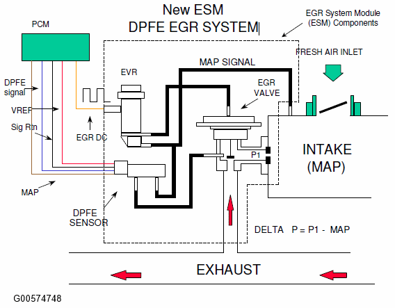
In the 2002.5 MY, Ford introduced a revised DPFE system. It functions in the same manner as the conventional DPFE system; however, the various system components have been combined into a single component called the EGR System Module (ESM). This arrangement increases system reliability while reducing cost. By relocating the EGR orifice from the exhaust to the intake, the downstream pressure signal measures Manifold Absolute Pressure (MAP). The ESM will provide the PCM with a differential DPFE signal, identical to the conventional DPFE system. The DPFE signal is obtained by electrically subtracting the MAP and P1 pressure signals and providing this signal to the DPFE input on the PCM. 2003 MY and later implementations of the ESM system has a separate input to the PCM for the MAP sensor signal.
 Courtesy of Courtesy of
|
 Courtesy of Courtesy of
|
The ESM Delta Pressure Feedback EGR Monitor is a series of electrical tests and functional tests that monitor various aspects of EGR system operation.
First, the Delta Pressure Feedback EGR (DPFE) sensor input circuit is checked for out of range values (P1400 or P0405, P1401 or P0406). The Electronic Vacuum Regulator (EVR) output circuit is checked for opens and shorts (P1409 or P0403).
EGR ELECTRICAL CHECK OPERATION
| DTCs |
P1400 or P0405 - DPFE Circuit Low
P1401 or P0406 - DPFE Circuit High
P1409 or P0403 - EVR circuit open or shorted |
| Monitor execution |
Continuous, during EGR monitor |
| Monitor Sequence |
None |
| Sensors OK |
|
| Monitoring Duration |
4 seconds to register a malfunction |
TYPICAL EGR ELECTRICAL CHECK ENTRY CONDITIONS
TYPICAL EGR ELECTRICAL CHECK MALFUNCTION THRESHOLDS
DPFE sensor outside voltage: > 4.96 volts, < 0.0489 volts
EVR solenoid smart driver status indicates open/short |
DPFE SENSOR TRANSFER FUNCTION
| ESM DPFE volts = Vref [(0.683 * Delta Pressure) + 10 ] / 100 |
| Volts |
A/D Counts in PCM |
Delta Pressure, Inches H 2
O |
| 0.0489 |
10 |
-13.2 |
| 0.26 |
53 |
-7.0 |
| 0.5 |
102 |
0 |
| 0.74 |
151 |
7.0 |
| 1.52 |
310 |
30 |
| 2.55 |
521 |
60 |
| 3.57 |
730 |
90 |
| 4.96 |
1015 |
130.7 |
NOTE:
EGR normally has large amounts of water vapor that are the result of the engine combustion process. During cold ambient temperatures, under some circumstances, water vapor can freeze in the DPFE sensor, hoses, as well as other components in the EGR system. In order to prevent MIL illumination for temporary freezing, the following logic is used:
If an EGR system malfunction is detected above 32 °F, the EGR system and the EGR monitor is disabled for the current driving cycle. A DTC is stored and the MIL is illuminated if the malfunction has been detected on two consecutive driving cycles.
If an EGR system malfunction is detected below 32 °F, only the EGR system is disabled for the current driving cycle. A DTC is not stored and the I/M readiness status for the EGR monitor will not change. The EGR monitor, however, will continue to operate. If the EGR monitor determined that the malfunction is no longer present (i.e., the ice melts), the EGR system will be enabled and normal system operation will be restored.
The ESM may provide the PCM with a separate, analog Manifold Absolute Pressure Sensor (MAP) signal. For the 2006 MY, the MAP signal has limited use within the PCM. It may be used to read BARO (key on, then updated at high load conditions while driving) or to modify requested EGR rates. Note that if the MAP pressure-sensing element fails in the ESM fails, the DPFE signal is also affected. Therefore, this MAP test is only checking the circuit from the MAP sensing element to the PCM.
The MAP sensor is checked for opens, shorts, or out-of-range values by monitoring the analog-to-digital (A/D) input voltage.
MAP SENSOR CHECK OPERATION
| DTCs |
P0107 (low voltage), P0108 (high voltage) |
| Monitor execution |
continuous |
| Monitor Sequence |
None |
| Sensors OK |
not applicable |
| Monitoring Duration |
5 seconds to register a malfunction |
MAP ELECTRICAL CHECK ENTRY CONDITIONS
| Battery voltage > 11.0 volts |
TYPICAL MAP SENSOR CHECK MALFUNCTION THRESHOLDS
| Voltage < 0.024 volts or voltage > 4.96 volts |
On ESM DPFE systems, after the vehicle is started, the differential pressure indicated by the ESM DPFE sensor at idle, at zero EGR flow is checked to ensure that both hoses to the ESM DPFE sensor are connected. At idle, the differential pressure should be zero (both hoses see intake manifold pressure). If the differential pressure indicated by the ESM DPFE sensor exceeds a maximum threshold or falls below a minimum threshold, an upstream or downstream hose malfunction is indicated (P1405, P1406).
ESM DPFE EGR HOSE CHECK OPERATION
| DTCs |
P1405 - Upstream Hose Off or Plugged
P1406 - Downstream Hose Off or Plugged |
| Monitor execution |
once per driving cycle |
| Monitor Sequence |
after electrical checks completed |
| Sensors OK |
MAF |
| Monitoring Duration |
10 seconds to register a malfunction |
TYPICAL ESM DPFE EGR HOSE CHECK ENTRY CONDITIONS
| Entry Condition |
Minimum |
Maximum |
| EVR Duty Cycle (EGR commanded off) |
0% |
0% |
| Closed throttle (warm engine idle) |
|
|
| Engine Coolant Temperature |
150 ° |
220 °F |
TYPICAL ESM EGR HOSE CHECK MALFUNCTION THRESHOLDS
| DPFE sensor voltage: < -0.122 volts (-11.06 in H2
O), > 4.69 volts (122.82 in H2
O) |
J1979 MODE $06 DATA
| Monitor ID |
Test ID |
Description for ESM DPFE |
Units |
| $32 |
$82 |
Delta pressure for upstream hose test and threshold (P1405) |
kPa |
| $32 |
$83 |
Delta pressure for downstream hose test and threshold (P1406) |
kPa |
NOTE:
OBD monitor ID $32, Test ID $82 (upstream hose test) may erroneously show a failing test result when no P1405 DTC is present. This is cause by in incorrect max limit in the software. The incorrect max limit will show a negative value (approx -32 kPa). The correct max limit will show a positive value (approx. +32 kPa). Early production vehicles may exhibit this issue until the software is corrected by a production running change or service fix.
Next, the differential pressure indicated by the DPFE sensor is also checked at idle with zero requested EGR flow to perform the high flow check. If the differential pressure exceeds a calibratable limit, it indicates a stuck open EGR valve or debris temporarily lodged under the EGR valve seat (P0402).
EGR STUCK OPEN CHECK OPERATION
| DTCs |
P0402 |
| Monitor execution |
once per driving cycle |
| Monitor Sequence |
done after hose tests completed |
| Sensors OK |
CPS, ECT, IAT, MAF, TP, MAP (P0106/7/8) |
| Monitoring Duration |
10 seconds to register a malfunction |
TYPICAL EGR STUCK OPEN CHECK ENTRY CONDITIONS
| Entry Condition |
Minimum |
Maximum |
| EVR Duty Cycle (EGR commanded off) |
0% |
0% |
| Engine RPM (after EGR enabled) |
at idle |
Idle |
TYPICAL EGR STUCK OPEN CHECK MALFUNCTION THRESHOLDS
| DPFE sensor voltage at idle versus engine-off signal: > 0.6 volts |
J1979 MODE $06 DATA
| Monitor ID |
Test ID |
Description for ESM DPFE |
Units |
| $32 |
$84 |
Delta pressure for stuck open test and threshold (P0402) |
kPa |
After the vehicle has warmed up and normal EGR rates are being commanded by the PCM, the low flow check is performed. Since the EGR system is a closed loop system, the EGR system will deliver the requested EGR flow as long as it has the capacity to do so. If the EVR duty cycle is very high (greater than 80% duty cycle), the differential pressure indicated by the DPFE sensor is evaluated to determine the amount of EGR system restriction. If the differential pressure is below a calibratable threshold, a low flow malfunction is indicated (P0401).
EGR FLOW CHECK OPERATION
| DTCs |
P0401 - Insufficient Flow |
| Monitor execution |
once per driving cycle |
| Monitor Sequence |
done after P0402 completed |
| Sensors OK |
CPS, ECT, IAT, MAF, TP, MAP (P0106/7/8) |
| Monitoring Duration |
70 seconds to register a malfunction |
TYPICAL EGR FLOW CHECK ENTRY CONDITIONS
| Entry Condition |
Minimum |
Maximum |
| EVR Duty Cycle |
80% |
100% |
| Engine RPM |
|
2500 rpm |
| Mass Air Flow Rate of Change |
|
6% program loop |
| Inferred manifold vacuum |
6 in Hg |
10 in Hg |
TYPICAL EGR FLOW CHECK MALFUNCTION THRESHOLDS
| DPFE sensor voltage: < 6 in H2
O |
J1979 MODE $06 DATA
| Monitor ID |
Test ID |
Description for ESM DPFE |
Units |
| $32 |
$85 |
Delta pressure for flow test and threshold (P0401) |
kPa |
I/M Readiness Indication
If the inferred ambient temperature is less than 32 °F, or greater than 140 °F, or the altitude is greater than 8, 000 feet (BARO < 22.5 "Hg), the EGR monitor cannot be run reliably. In these conditions, a timer starts to accumulate the time in these conditions. If the vehicle leaves these extreme conditions, the timer starts decrementing, and, if conditions permit, will attempt to complete the EGR flow monitor. If the timer reaches 500 seconds, the EGR monitor is disabled for the remainder of the current driving cycle and the EGR Monitor I/M Readiness bit will be set to a "ready" condition after one such driving cycle. Starting in the 2002 MY, vehicles will require two such driving cycles for the EGR Monitor I/M Readiness bit to be set to a "ready" condition.