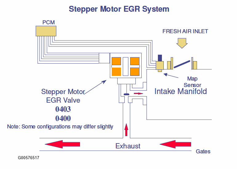
The Electric Stepper Motor EGR System uses an electric stepper motor to directly actuate an EGR valve rather than using engine vacuum and a diaphragm on the EGR valve. The EGR valve is controlled by commanding from 0 to 52 discreet increments or "steps" to get the EGR valve from a fully closed to fully open position. The position of the EGR valve determines the EGR flow. Control of the EGR valve is achieved by a non-feedback, open loop control strategy. Because there is no EGR valve position feedback, monitoring for proper EGR flow requires the addition of a MAP sensor.
 Courtesy of FORD MOTOR CO. Courtesy of FORD MOTOR CO.
|
The Stepper Motor EGR Monitor consists of an electrical and functional test that checks the stepper motor and the EGR system for proper flow.
The stepper motor electrical test is a continuous check of the four electric stepper motor coils and circuits to the PCM. A malfunction is indicated if an open circuit, short to power, or short to ground has occurred in one or more of the stepper motor coils for a calibrated period of time. If a malfunction has been detected, the EGR system will be disabled, and additional monitoring will be suspended for the remainder of the driving cycle, until the next engine start-up.
EGR STEPPER MONITOR ELECTRICAL CHECK OPERATION
| DTCs |
P0403 |
| Monitor execution |
continuous |
| Monitor Sequence |
none |
| Sensors OK |
|
| Monitoring Duration |
4 seconds to register a malfunction |
STEPPER MOTOR ELECTRICAL CHECK ENTRY CONDITIONS
| Battery voltage > 11.0 volts |
TYPICAL EGR ELECTRICAL CHECK MALFUNCTION THRESHOLDS
| "Smart" Coil Output Driver status indicates open or short to ground, or short to power |
EGR flow is monitored using an analog Manifold Absolute Pressure Sensor (MAP). If a malfunction has been detected in the MAP sensor, the EGR monitor will not perform the EGR flow test.
The MAP sensor is checked for opens, shorts, or out-of-range values by monitoring the analog-to-digital (A/D) input voltage.
MAP SENSOR CHECK OPERATION
| DTCs |
P0107 (low voltage), P0108 (high voltage) |
| Monitor execution |
continuous |
| Monitor Sequence |
none |
| Sensors OK |
not applicable |
| Monitoring Duration |
5 seconds to register a malfunction |
MAP ELECTRICAL CHECK ENTRY CONDITIONS
| Battery voltage > 11.0 volts |
TYPICAL MAP SENSOR CHECK MALFUNCTION THRESHOLDS
| Voltage < 0.024 volts or voltage > 4.96 volts |
The MAP sensor is also checked for rational values. The value of inferred MAP is checked against the actual value of MAP at idle and non-idle engine operating conditions.
MAP SENSOR RATIONALITY CHECK OPERATION
| DTCs |
P0106 |
| Monitor execution |
continuous |
| Monitor Sequence |
none |
| Sensors OK |
not applicable |
| Monitoring Duration |
10 seconds to register a malfunction |
TYPICAL MAP RATIONALITY CHECK ENTRY CONDITIONS
| Entry Condition |
Minimum |
Maximum |
| Change in load |
|
5% |
| Engine RPM |
500 rpm |
1800 rpm |
TYPICAL MAP RATIONALITY CHECK MALFUNCTION THRESHOLDS
| Difference between inferred MAP and actual MAP > 10 in Hg |
The MAP sensor is also checked for intermittent MAP faults.
MAP SENSOR INTERMITTENT CHECK OPERATION
| DTCs |
P0109 (non-MIL) |
| Monitor Execution |
Continuous |
| Monitor Sequence |
None |
| Sensors OK |
not applicable |
| Monitoring Duration |
2 seconds to register a malfunction |
TYPICAL MAP INTERMITTENT CHECK MALFUNCTION THRESHOLDS
| Voltage < 0.024 volts or voltage > 4.96 volts |
When EGR is delivered into the intake manifold, intake manifold vacuum is reduced and thus manifold absolute pressure (MAP) is increased. A MAP sensor and inferred MAP are used by this monitor to determine how much EGR is flowing. A MAP sensor located in the intake manifold measures the pressure when EGR is being delivered and when EGR is not being delivered. The pressure difference between EGR-on and EGR-off is calculated and averaged. If the vehicle also has a MAF sensor fitted, then the monitor also calculates and averages an inferred MAP value in the above calculation and resulting average. After a calibrated number of EGR-on and EGR-off cycles are taken, the measured and inferred MAP values are added together and compared to a minimum threshold to determine if a flow failure (P0400) in the EGR system has occurred.
EGR FLOW CHECK OPERATION
| DTCs |
P0400 |
| Monitor execution |
once per driving cycle |
| Monitor Sequence |
None |
| Sensors OK |
CPS, ECT, IAT, MAF, MAP (P0106/7/8), TP, BARO not available yet |
| Monitoring Duration |
200 seconds (600 data samples) |
TYPICAL EGR FLOW CHECK ENTRY CONDITIONS
| Entry Condition |
Minimum |
Maximum |
| Engine RPM |
1400 rpm |
2600 rpm |
| Inferred Ambient Air Temperature |
32 °F |
140 °F |
| Engine Coolant Temperature |
80 °F |
250 °F |
| Engine RPM Steady (change/0.050 sec) |
|
100 rpm |
| MAP Steady (change/0.050 sec) |
|
0.5 in "Hg |
| Engine Load Steady (change/0.050 sec) |
|
1.5% |
| BARO |
22.5 "Hg |
|
| Intake Manifold Vacuum |
9.0 "Hg |
16.0 "Hg |
| Vehicle Speed |
35 MPH |
70 MPH |
| Engine Throttle Angle steady (absolute change) |
0.0 degrees |
4.0 degrees |
TYPICAL EGR FLOW CHECK MALFUNCTION THRESHOLDS
J1979 MODE $06 DATA
| Monitor ID |
Test ID |
Description |
Units |
| $31 |
$82 |
Normalized MAP differential (range 0 - 2) (P0400) |
unitless |
I/M Readiness Indication
If the inferred ambient temperature is less than 20 °F, greater than 130 °F, or the altitude is greater than 8, 000 feet (BARO < 22.5 "Hg), the EGR flow test cannot be reliably done. In these conditions, the EGR flow test is suspended and a timer starts to accumulate the time in these conditions. If the vehicle leaves these extreme conditions, the timer starts decrementing, and, if conditions permit, will attempt to complete the EGR flow monitor. If the timer reaches 800 seconds, the EGR flow test is disabled for the remainder of the current driving cycle and the EGR Monitor I/M Readiness bit will be set to a "ready" condition after one such driving cycle. Two such consecutive driving cycles are required for the EGR Monitor I/M Readiness bit to be set to a "ready" condition.