October 30: LEMON manuals on a temporary server, it is slow and having issues, download the manuals you need! Later in November we will switch back to the fast server.
Ignition Timing
- Warm engine to normal operating temperature. Turn engine off, but keep ignition on for 5 seconds. Restart engine, and raise engine speed to 2000 RPM for 5 minutes. Return to idle. Ensure all accessories are off and idle speed is within specification. Adjust idle speed first if it is not within specification. See IDLE SPEED
under IDLE SPEED & MIXTURE.
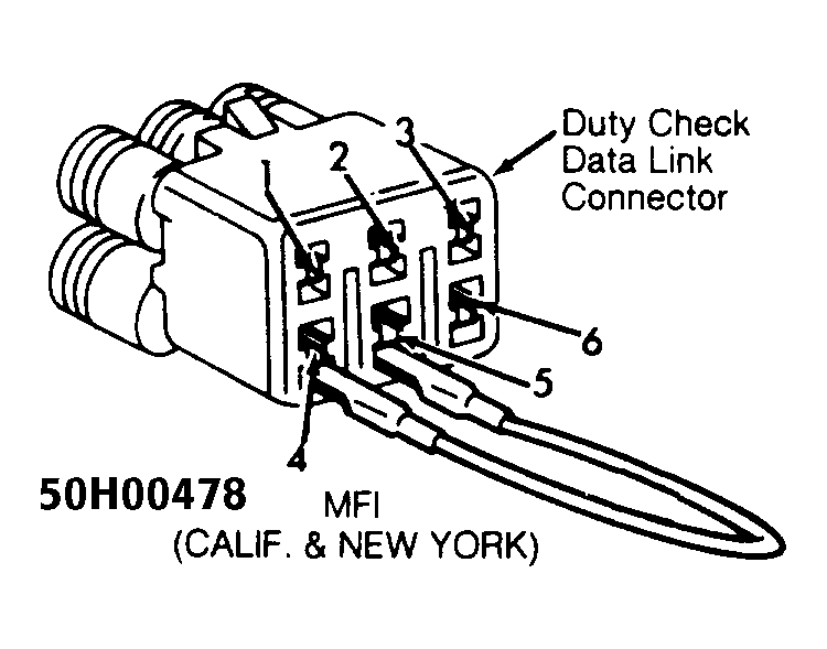
- Connect timing light to No. 1 spark plug wire. Remove cap from duty check Data Link Connector (DLC), located near fusible link box, by battery. On TBI (Federal), connect a jumper wire between terminals "C" (Black wire) and "D" (Blue/Red wire) of duty check DLC. See Fig 2
. On MFI (Calif. and New York), connect a jumper wire between terminals No. 4 (Black wire) and No. 5 (Blue/Red wire) of duty check DLC. See Fig 2
.
- On all models, check timing mark alignment on crankshaft pulley with timing marks on timing belt cover. Ignition timing must be within specification. See IGNITION TIMING SPECIFICATIONS
.
- If ignition timing is not as specified, loosen distributor hold-down flange bolts, and rotate distributor to obtain correct ignition timing. Tighten distributor hold-down flange bolts to 15 ft. lbs. (20 N.m). Recheck ignition timing.
- Turn engine off. Remove jumper wire and install cap on duty check DLC. Remove test equipment.
 Courtesy of GENERAL MOTORS CORP.
 Courtesy of GENERAL MOTORS CORP.
IGNITION TIMING SPECIFICATIONS
| Application |
Man. Trans. |
Auto. Trans. |
| TBI (Federal) |
8 @ 800 |
8 @ 800 |
| MFI (Calif. & New York) |
5 @ 800 |
5 @ 800 |