Audio Unit Connector for Inputs and Outputs
WARNING: This page is about a different car, the 2009 Acura MDX, 2008 Acura MDX, and 2007 Acura MDX. However, it is still accessible from the selected car via links, so may be relevant.
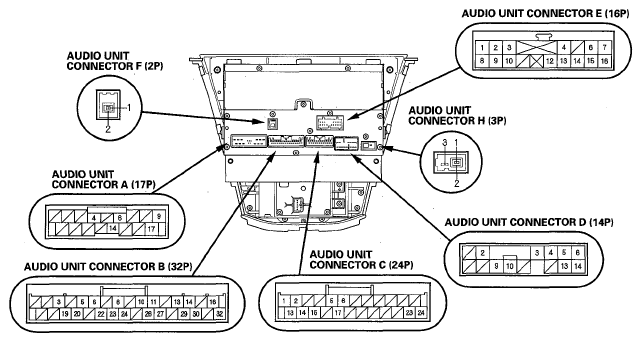
When replacing an audio unit connector, match the wires to the cavities listed in the following tables.
With navigation/With rear entertainment system
 Courtesy of AMERICAN HONDA MOTOR CO., INC.
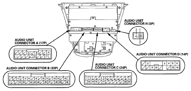
With navigation/Without rear entertainment system
 Courtesy of AMERICAN HONDA MOTOR CO., INC.
When replacing an audio unit connector, match the wires to the cavities listed in the following tables.
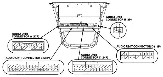
Without navigation/Without rear entertainment system
 Courtesy of AMERICAN HONDA MOTOR CO., INC.
 Courtesy of AMERICAN HONDA MOTOR CO., INC.
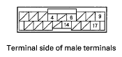
 AUDIO UNIT A (17P) CONNECTOR TERMINAL REFERENCE
| Cavity |
Wire |
Connects to |
| A4 |
LT GRN |
Rear controller and screen (SCTY4) |
| Navigation display unit (SCTY4) |
| RED |
MICU (SCTY 1) |
| A6 |
LT BLU |
MICU (K-LINE) |
| A9 |
BLK |
Ground (G504) |
| A14 |
PUR |
ACC (audio power supply) |
| A17 |
WHT |
Constant power |
 Courtesy of AMERICAN HONDA MOTOR CO., INC.
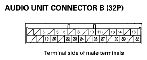
 AUDIO UNIT B (32P) CONNECTOR TERMINAL REFERENCE
| Cavity |
Wire |
Connects to |
| B3 |
BRN |
Audio remote ground |
| B5 |
GRN |
Stereo amplifier (RS485+) |
| B6 |
BLU |
Stereo amplifier (RS485-) |
| B8 |
RED |
Stereo amplifier (FL PRE IN-) |
| B10 |
PNK |
Stereo amplifier (FR PRE IN-) |
| B11 |
PUR |
Stereo amplifier (RL PRE IN-) |
| B13 |
YEL |
Stereo amplifier (RR PRE IN-) |
| B14 |
RED |
Stereo amplifier (SW PRE IN-) |
| B16 |
PNK |
Stereo amplifier (CTR PRE IN-) |
| B19 |
ORN |
Audio remote |
| B20 |
PNK |
Stereo amplifier (RS 485 GND) |
| B22 |
BRN |
Stereo amplifier (RS 485 SH) |
| B23 |
LT GRN |
Stereo amplifier (+B) |
| B24 |
GRN |
Stereo amplifier (FL PRE IN+) |
| B26 |
BLU |
Stereo amplifier (FR PRE IN+) |
| B27 |
LT BLU |
Stereo amplifier (RL PRE IN+) |
| B29 |
BRN |
Stereo amplifier (RR PRE IN+) |
| B30 |
GRN |
Stereo amplifier (SW PRE IN+) |
| B32 |
BLU |
Stereo amplifier (CTR PRE IN+) |
 Courtesy of AMERICAN HONDA MOTOR CO., INC.
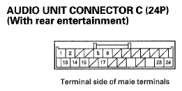
 AUDIO UNIT C (24P) CONNECTOR TERMINAL REFERENCE
| Cavity |
Wire |
Connects to |
| C1 |
PNK |
Auxiliary jack assembly (AUX AUDIO R/L GND) |
| C2 |
BRN |
Auxiliary jack assembly (AUX AUDIO R/L SH) |
| C5 |
PUR |
XM receiver, HandsFreeLink control unit (LINE OUT-) |
| C6 |
BRN |
XM receiver, HandsFreeLink control unit (LINE OUT SH) |
| C13 |
BLU |
Auxiliary jack assembly (AUX AUDIO R) |
| C14 |
GRN |
Auxiliary jack assembly (AUX AUDIO L) |
| C15 |
WHT |
Auxiliary jack assembly (CONN CHK) |
| C17 |
LT BLU |
XM receiver, HandsFreeLink control unit (LINE OUT+) |
| C23 |
LT GRN |
XM receiver (B-CAN) |
| C24 |
BLU |
Climate control unit (HVAC BUS) |
 Courtesy of AMERICAN HONDA MOTOR CO., INC.
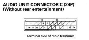
 AUDIO UNIT C (24P) CONNECTOR TERMINAL REFERENCE
| Cavity |
Wire |
Connects to |
| C1 |
RED |
Auxiliary jack assembly (AUX SIG GND) |
| C2 |
BRN |
Auxiliary jack assembly (SH AUX) |
| C5 |
PUR |
XM receiver, HandsFreeLink control unit (LINE OUT-) |
| C6 |
BRN |
XM receiver, HandsFreeLink control unit (LINE OUT SH) |
| C13 |
BLK |
Auxiliary jack assembly (AUX RCH) |
| C14 |
WHT |
Auxiliary jack assembly (AUX LCH) |
| C15 |
LT BLU |
Auxiliary jack assembly (AUX DET) |
| C17 |
LT BLU |
XM receiver, HandsFreeLink control unit (LINE OUT+) |
| C23 |
LT GRN |
XM receiver (B-CAN) |
| C24 |
BLU |
Climate control unit (HVAC BUS) |
 Courtesy of AMERICAN HONDA MOTOR CO., INC.
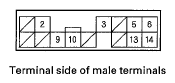
 AUDIO UNIT D (14P) CONNECTOR TERMINAL REFERENCE
| Cavity |
Wire |
Connects to |
| D2 |
RED |
XM receiver (ACC) |
| D3 |
BRN |
XM receiver. Navigation unit, Navigation display unit (GANET BUS SH) |
| D4 |
BRN |
XM receiver (GANET AUDIO SH) |
| D5 |
RED |
XM receiver (GANET AUDIO R+) |
| D6 |
BLK |
XM receiver (GANET AUDIO L+) |
| D9 |
GRN |
XM receiver, Navigation unit, Navigation display unit (GANET BUS+) |
| D10 |
RED |
XM receiver, Navigation unit, Navigation display unit (GANET BUS -) |
| D13 |
WHT |
XM receiver (GANET AUDIO R-) |
| D14 |
GRN |
XM receiver (GANET AUDIO L-) |
 Courtesy of AMERICAN HONDA MOTOR CO., INC.
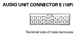
 AUDIO UNIT E (16P) CONNECTOR TERMINAL REFERENCE
| Cavity |
Wire |
Connects to |
| E1 |
BRN |
Auxiliary jack assembly (AUX VIDEO IN SH) |
| E2 |
LT BLU |
Auxiliary jack assembly (AUX VIDEO IN GND) |
| E3 |
BRN |
Rear controller and screen (RR NTSC SH) |
| E4 |
YEL |
Rear controller and screen (SYSTEM ACC) |
| E6 |
BRN |
Rear controller and screen (RR BUS SH) |
| E7 |
PUR |
Rear controller and screen (RR BUS-) |
| E8 |
PUR |
Auxiliary jack assembly (AUX VIDEO IN) |
| E9 |
PNK |
Rear controller and screen (RR NTSC GND) |
| E10 |
BLU |
Rear controller and screen (RR NTSC) |
| E12 |
BLK |
Rear controller and screen (RES AUDIO OUT R) |
| E13 |
BRN |
Rear controller and screen (RES AUDIO OUT SH) |
| E14 |
RED |
Rear controller and screen (RES AUDIO OUT L) |
| E15 |
WHT |
Rear controller and screen (RES AUDIO OUT GND) |
| E16 |
LT BLU |
Rear controller and screen (RR BUS+) |
 Courtesy of AMERICAN HONDA MOTOR CO., INC.
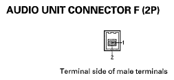
 AUDIO UNIT F (2P) CONNECTOR TERMINAL REFERENCE
| Cavity |
Wire |
Connects to |
| F1 |
-- |
Rear controller and screen (DIG AUDIO SIG) |
| F2 |
-- |
Rear controller and screen (DIG AUDIO SH) |
 Courtesy of AMERICAN HONDA MOTOR CO., INC.
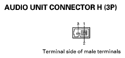
 AUDIO UNIT H (3P) CONNECTOR TERMINAL REFERENCE
| Cavity |
Wire |
Connects to |
| H1 |
-- |
Antenna, module unit (SIG) |
| H2 |
-- |
Antenna module unit (SH (AM/FM)) |
| H3 |
-- |
Antenna module unit (ANT+B) |