Park Pin Switch Replacement
- Remove the shift lever assembly (see SHIFT LEVER REMOVAL
).
- Remove the harness clamps from the shift lever bracket, and remove the harnesses from the harness clamps.
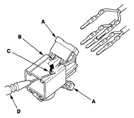
- Pry up the lock covers (A) of the D3 switch/shift lock solenoid/park pin switch connector (B).
 Courtesy of AMERICAN HONDA MOTOR CO., INC.
- Remove the terminal from the connector by pushing the lock tab (C) up in the connector using a thin blade screwdriver (D). Remove all six terminals, and replace the connector.
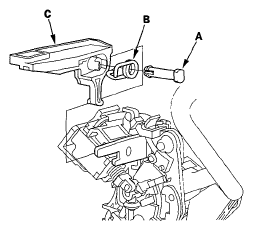
- Remove the shift lock release pin (A), spring (B), and the shift lock release (C).
 Courtesy of AMERICAN HONDA MOTOR CO., INC.
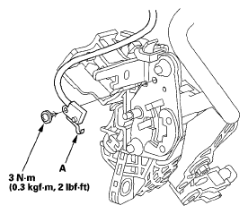
- Remove the park pin switch (A).
 Courtesy of AMERICAN HONDA MOTOR CO., INC.
- Install a new park pin switch by aligning the tab with the positioning hole on the shift lever position guide. Apply non-hardening thread lock sealant to the screw, then secure the park pin switch with the screw.
- Apply silicone grease to the shift lock release pin and spring, and install the shift lock release, spring, and pin.
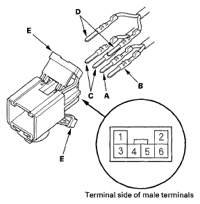
- Install the RED harness terminal (A) of the shift lock solenoid in the No. 5 cavity, and the BLK harness terminal (B) in the No. 6 cavity.
 Courtesy of AMERICAN HONDA MOTOR CO., INC.
- Install the D3 switch harness terminals (WHT) (C) in the No. 3 and No. 4 cavities. Either D3 switch harness terminal can be installed in the No. 3 and No. 4 cavities.
- Install the park pin switch harness terminals (BLK) (D) in the No. 1 and No. 2 cavities. Either park pin switch harness terminal can be installed in the No. 1 and No. 2 cavities.
- Make sure that all six terminals lock securely, then install the lock covers (E) in place securely.
- Route the harnesses (A) through the guides (B).
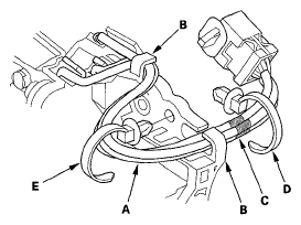 Courtesy of AMERICAN HONDA MOTOR CO., INC.
- Align the marks (C) on each harness, and tie the harness together into bundle with a new harness clamp (D) over the marks.
- Tie the harness together into bundle with a new harness clamp, then install the harness clamp (E) on the shift lever bracket.
- Install the shift lever assembly (see SHIFT LEVER INSTALLATION
).