October 30: LEMON manuals on a temporary server, it is slow and having issues, download the manuals you need! Later in November we will switch back to the fast server.
Vehicle Speed Sensor Replacement
- Remove the air cleaner (see
AIR CLEANER ELEMENT INSPECTION/REPLACEMENT
).
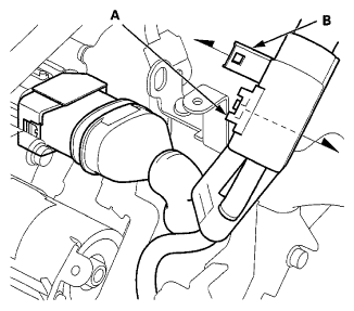
- Remove the IMA motor power cable clamp (A) from the clamp bracket (B).
 Courtesy of AMERICAN HONDA MOTOR CO., INC.
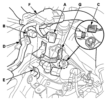
- Disconnect the transmission range switch 8P connector (A), the CVT output shaft (driven pulley) speed sensor 3P connector (B), and the vehicle speed sensor 3P connector (C).
 Courtesy of AMERICAN HONDA MOTOR CO., INC.
- Remove the harness holder (D) from the clamp bracket (E), and remove the harness cover (F) from the clamp bracket (G).
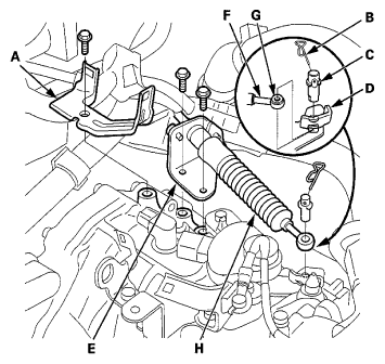
- Remove the clamp bracket (A).
 Courtesy of AMERICAN HONDA MOTOR CO., INC.
- Remove the lock pin (B) and the control pin (C) from the selector control lever (D).
- Remove the bolts securing the shift cable holder (E), then separate the shift cable end (F) from the selector control lever. Check the shift cable end collar (G) for wear or damage, and replace the shift cable (H) (see SHIFT CABLE REPLACEMENT
) if necessary.
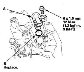
- Remove the vehicle speed sensor (A) and the O-ring (B).
 Courtesy of AMERICAN HONDA MOTOR CO., INC.
- Install a new O-ring on a new vehicle speed sensor, then install the vehicle speed sensor in the transmission housing.
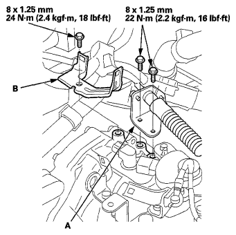
- Secure the shift cable holder (A) on the transmission with the bolts.
 Courtesy of AMERICAN HONDA MOTOR CO., INC.
- Install the clamp bracket (B).
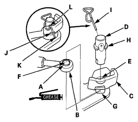
- Apply molybdenum grease to the hole in the shift cable end collar (A). Attach the shift cable end (B) to the selector control lever (C). Insert the control pin (D) through the selector control lever hole (E), through the shift cable end collar hole (F), and into the selector control lever slotted hole (G) in the direction shown. Push the control pin until its flange (H) contacts the selector control lever surface.
 Courtesy of AMERICAN HONDA MOTOR CO., INC.
- Insert the lock pin (I) in the direction shown through the control pin hole and out the opening (J) of the selector control lever so that the hooked end (K) of the lock pin locks into the countersunk hole (L) of the control pin.
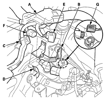
- Install the harness cover (A) to the clamp bracket (B), and install the harness holder (C) to the clamp bracket (D).
 Courtesy of AMERICAN HONDA MOTOR CO., INC.
- Connect the transmission range switch 8P connector (E), the CVT output shaft (driven pulley) speed sensor 3P connector (F), and the vehicle speed sensor 3P connector (G).
NOTE:
Check the connector for rust, dirt, or oil, and clean or repair if necessary, then connect the connector securely.
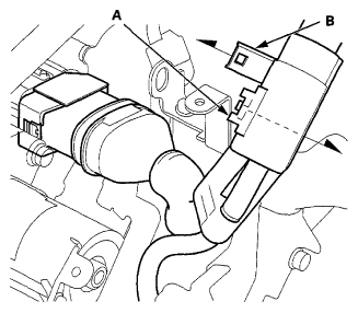
- Install the IMA motor power cable clamp (A) to the clamp bracket (B).
 Courtesy of AMERICAN HONDA MOTOR CO., INC.
- Install the air cleaner (see
AIR CLEANER ELEMENT INSPECTION/REPLACEMENT
).