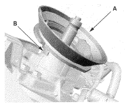
- Install the pinion shaft grommet (A). Align the lug portion (B) in the pinion shaft grommet with the steering gearbox.
 Courtesy of AMERICAN HONDA MOTOR CO., INC.
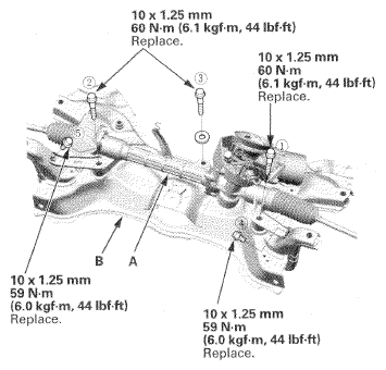
- Place the steering gearbox (A) on the front subframe (B).
 Courtesy of AMERICAN HONDA MOTOR CO., INC.
- Loosely install new gearbox mounting bolts, then tighten the bolts to the specified torque in the sequence as shown.
- Set the front subframe (A) mounting the steering gearbox on the transmission jack and support it.
 Courtesy of AMERICAN HONDA MOTOR CO., INC.
- Carefully raise the front subframe with the transmission jack, and pass the pinion shaft into the passenger's compartment.
NOTE:
- Be sure that the pinion shaft grommet (B) is securely in place. Make sure the lip of the pinion shaft grommet is not turned up. Incorrect installation can cause leakage of water and mud, or noise.
- Take care not to damage the lower arm ball joint boot with the edge of the knuckle, etc.
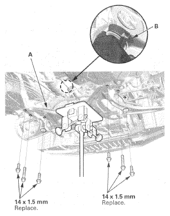
- Install the front subframe, then loosely tighten the new front subframe mounting bolts.
- Align the front subframe (see
FRONT SUBFRAME ALIGNMENT
).
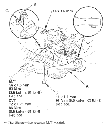
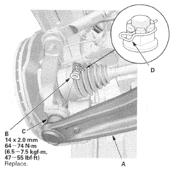
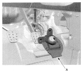
- Install the torque rod (A).
NOTE:
Be sure to install the torque rod with the "UP" mark facing up.
 Courtesy of AMERICAN HONDA MOTOR CO., INC.
- Install the bolt with the tab (B) on the bolt head aligned with the guide (C) on the front subframe, then tighten the new torque rod mounting bolt and nut in the numbered sequence shown.
- Remove the jack (A).
 Courtesy of AMERICAN HONDA MOTOR CO., INC.
- Tighten the torque rod mounting bolt and nut in the numbered sequence shown.
 Courtesy of AMERICAN HONDA MOTOR CO., INC.
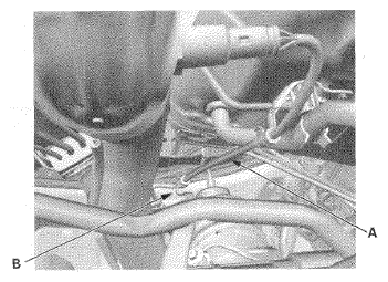
- Install the secondary HO2S wire (A) in the clamp (B).
 Courtesy of AMERICAN HONDA MOTOR CO., INC.
- Remove the vinyl tape from the connectors.
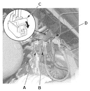
- Connect the torque sensor 6P connector (A) and the EPS motor angle sensor 8P connector (B).
 Courtesy of AMERICAN HONDA MOTOR CO., INC.
- Pull down the lever (C) of the EPS motor 3P connector (D), then confirm the connector is fully seated.
- Install the stabilizer links to the stabilizer bar (see
STABILIZER LINK REMOVAL/INSTALLATION
) on both sides.
- Install the splash shield (see
SPLASH SHIELD REPLACEMENT
).
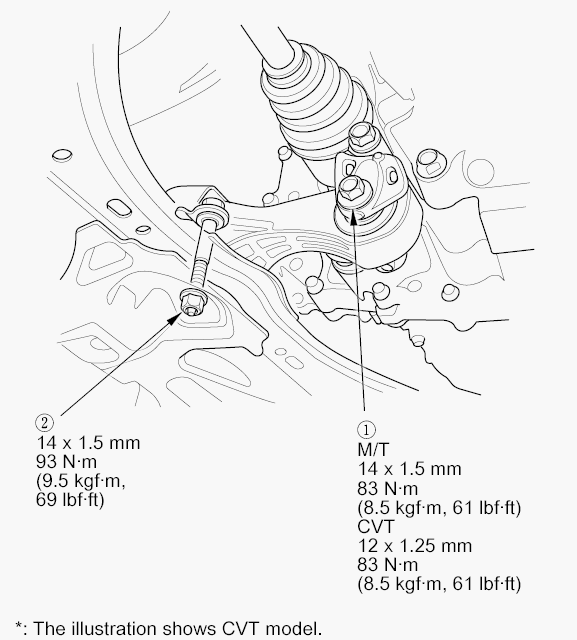
- Wipe off any grease contamination from the tapered section and threads of the ball joint. Connect the lower arm (A) to the knuckle. Install a new castle nut (B), and tighten it to the specified torque on both sides.
NOTE:
- Be careful not to damage the lower ball joint boot (C). Check the ball joint boot for deformation before connecting the knuckle.
- Torque the castle nut to the lower torque specification, then tighten it only far enough to align the slot with the joint pin clip hole. Do not align the castle nut by loosening it.
 Courtesy of AMERICAN HONDA MOTOR CO., INC.
- Install the lock pin (D) on both sides.
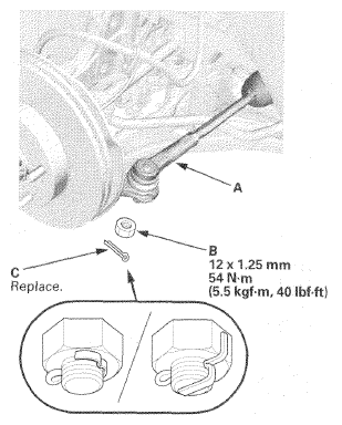
- Wipe off any grease contamination from the tapered section and threads of the tie-rod end ball joint. Connect the tie-rod end (A) to the knuckles. Install the nut (B), and tighten it to the specified torque on both sides.
 Courtesy of AMERICAN HONDA MOTOR CO., INC.
- Install a new cotter pin (C), and bend it as shown on both sides.
- Install the front wheels, then set the wheels in the straight ahead position.
NOTE:
Before installing the wheel, clean the mating surfaces of the brake disc and the inside of the wheel.
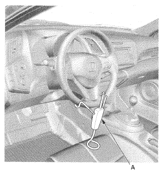
- Remove the steering wheel holder tool (A).
 Courtesy of AMERICAN HONDA MOTOR CO., INC.
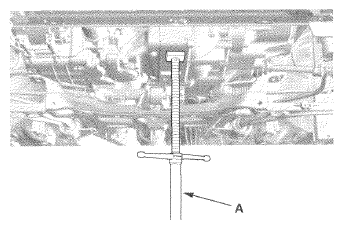
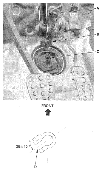
- Cut the wire (A), and slip the lower end of the steering joint (B) onto the pinion shaft (C) taking care to align the gap (D) within the angle.
 Courtesy of AMERICAN HONDA MOTOR CO., INC.
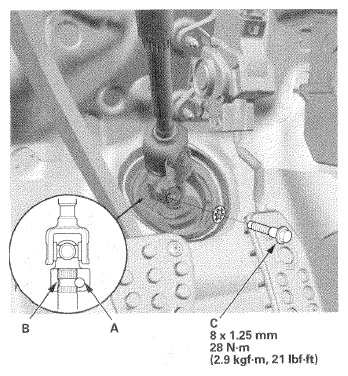
- Align the bolt hole (A) on the steering joint with the groove (B) around the pinion shaft, then loosely install the steering joint bolt (C). Be sure that the joint bolt is securely in the groove in the pinion shaft.
 Courtesy of AMERICAN HONDA MOTOR CO., INC.
- Pull on the steering joint to make sure that the steering joint is fully seated, then tighten the steering joint bolt to the specified torque.
- Install the steering joint cover (A).
NOTE:
Check the steering joint cover for damage and cracks. If the steering joint cover is cracked, replace the steering joint cover.
 Courtesy of AMERICAN HONDA MOTOR CO., INC.
- Do the 12 volt battery terminal reconnection procedure (see
12 VOLT BATTERY TERMINAL DISCONNECTION AND RECONNECTION
).
- After installation, do these checks:
- Start the engine, allow it to idle, and turn the steering wheel from lock to lock several times. Check that the EPS indicator does not come on.
- Check the steering wheel spoke angle. If steering spoke angles to the right and left are not equal (steering wheel and rack are not centered), correct the engagement of the joint/pinion shaft serrations, then adjust the front toe by turning the tie-rod ends, if necessary.
- Check the wheel alignment, and adjust it if necessary (see
WHEEL ALIGNMENT
).