DTC P2656: General Description
 Courtesy of HONDA, U.S.A., INC. Courtesy of HONDA, U.S.A., INC.
|
| Mode |
PCM sends command to the rocker arm oil control solenoid |
Rocker arm oil pressure switch (detected oil pressure) |
| Solenoid A (Bank 1) |
Solenoid B (Bank 1) |
Solenoid A (Bank 2) |
Switch A (Bank 1) |
Switch B (Bank 1) |
Switch A (Bank 2) |
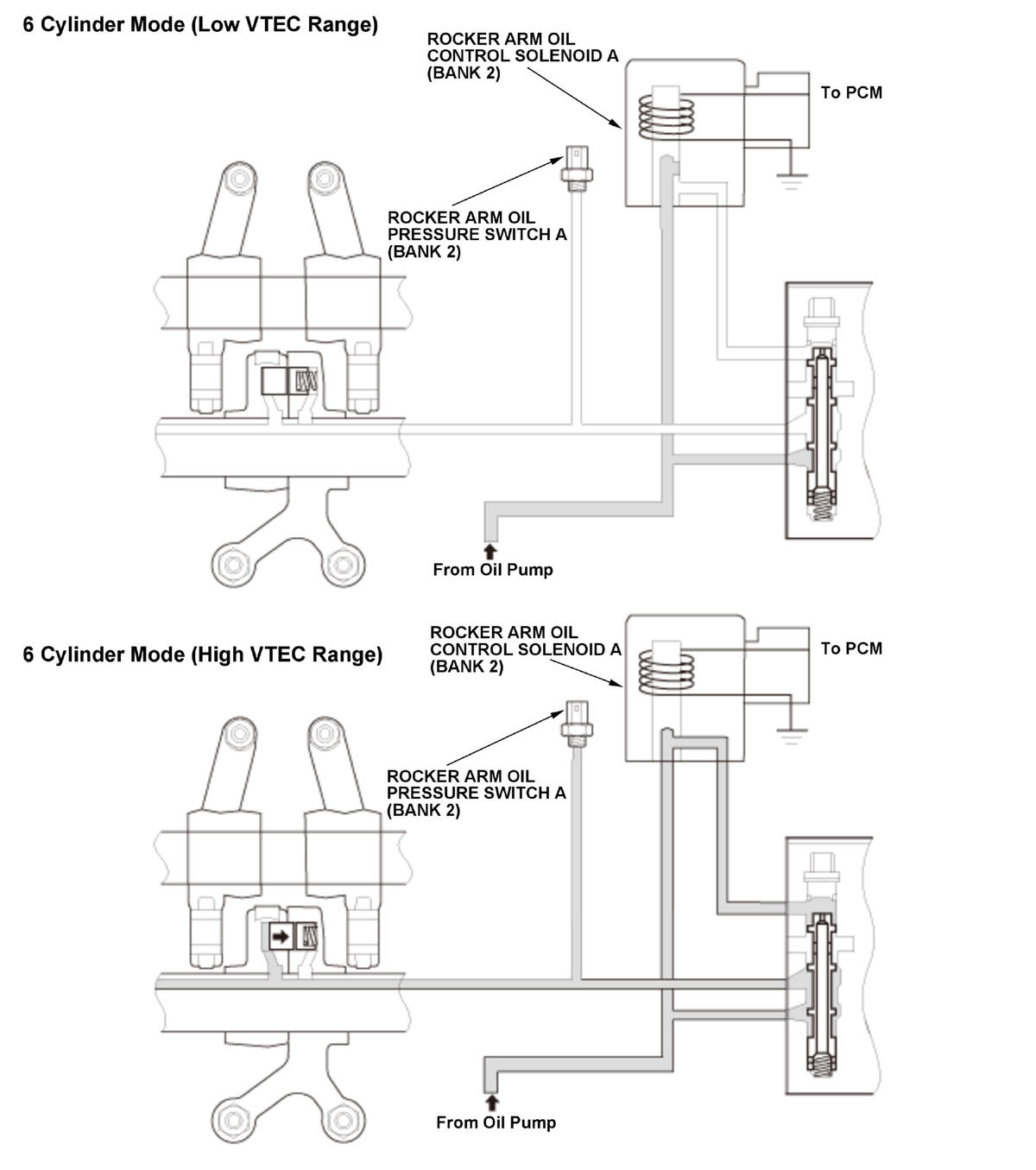
| 6 Cylinder Mode (Low VTEC Range) |
OFF |
OFF |
OFF |
ON (low) |
OFF (low) |
ON (low) |
| Mode |
PCM sends command to the rocker arm oil control solenoid |
Rocker arm oil pressure switch (detected oil pressure) |
| Solenoid A (Bank 1) |
Solenoid B (Bank 1) |
Solenoid A (Bank 2) |
Switch A (Bank 1) |
Switch B (Bank 1) |
Switch A (Bank 2) |
| 6 Cylinder Mode (High VTEC Range) |
ON |
OFF |
ON |
OFF (high) |
OFF (low) |
OFF (high) |
| 3 Cylinder Mode (3 Cylinders are paused) |
OFF |
ON |
OFF |
ON (low) |
ON (high) |
ON (low) |
The VTEC system activates the rocker arm oil control solenoid A (bank 2) with a command from the powertrain control module (PCM), and it charges/discharges the hydraulic circuit of the VTEC mechanism that switches valve timing between Low and High. The PCM monitors oil pressure in the hydraulic circuit of the VTEC mechanism using the rocker arm oil pressure switch A (bank 2) downstream of the rocker arm oil control solenoid A (bank 2). If there is a difference between the oil pressure condition in the hydraulic circuit determined by the PCM command and the oil pressure condition determined by the status of the rocker arm oil pressure switch A (bank 2), the system is considered faulty, and a DTC is stored.