Testing Procedure
- Turn ignition off. Connect HI-SCAN (PRO) or equivalent scan tool to Data Link Connector (DLC). DLC is located under left side of instrument panel, near kick panel. Using scan tool, retrieve DTCs. See RETRIEVING & CLEARING DIAGNOSTIC TROUBLE CODES
under DIAGNOSIS & TESTING. If DTC C1503 is set, clear DTC and go to next step.
- Test drive vehicle operating brake system under conditions which set DTC. Using scan tool, retrieve DTCs. If DTC C1503 resets, go to next step. If DTC C1503 does not reset, problem is probably intermittent. Check harness connectors, wiring harnesses and ABS components for intermittent problem. If problem is found, repair as necessary. After repair, retest system.
- Replace TCS switch. Using scan tool, clear DTC. Test drive vehicle operating brake system under conditions which set DTC. Using scan tool, retrieve DTCs. If DTC C1503 resets, go to next step. If DTC C1503 does not reset, TCS switch was stuck and testing is complete.
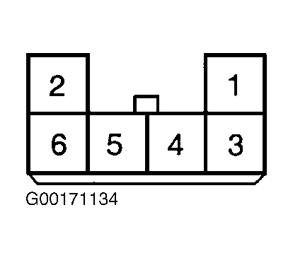
- Turn ignition on. Backprobing at TCS switch, measure voltage between ground and TCS switch harness connector terminal No. 3 (Pink wire). See Fig 1
. If battery voltage exists, leave ignition on and go to step 6
. If battery voltage does not exist, go to next step.
- Check for and repair open or short in Pink wire between TCS switch and fuse No. 28 (10-amp). Fuse is located in passenger compartment junction block. See WIRING DIAGRAMS
. After repair, retest system.
- Ensure TCS switch is in OFF position. Measure voltage between ground and TCS switch harness connector terminal No. 4 (Blue wire). If voltage reading is 4 volts, go to step 8
. If voltage reading is not 4 volts, leave ignition on and go to next step.
- Turn TCS switch to ON position. Measure voltage between ground and TCS switch harness connector terminal No. 4 (Blue wire). If voltage reading is 1.4 volts, go to next step. If voltage reading is not 1.4 volts, go to step 9
.
- Turn ignition off. Connect TCS switch harness connector. Access HECU. HECU is located at right rear corner of engine compartment, on firewall. Turn ignition on. Turn TCS switch to OFF position. Backprobing at HECU, measure voltage between ground and HECU connector terminal No. 15 (Blue wire). If voltage reading is 4 volts, go to step 10
. If voltage reading is not 4 volts, go to next step.
- Check for and repair open or short in Blue wire between HECU and TCS switch. See WIRING DIAGRAMS
. After repair, retest system.
- Replace HECU. See HYDRAULIC AND ELECTRONIC CONTROL UNIT
under REMOVAL & INSTALLATION. After repair, retest system.
 Courtesy of HYUNDAI MOTOR CO.