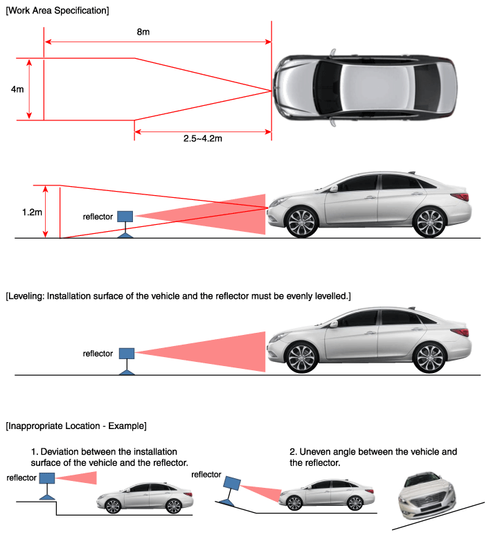
- Stop the vehicle horizontally at a flat place.
NOTE:
- Adjustment may not be accurate if the installation surface height and angle of the vehicle and reflector are different.
- Perform in an area with minimum clearance of 8m front, 4m sides, and 1.2m above the vehicle.
- Remove heavy objects from inside of the vehicle (seating area and trunk).
- Ensure that all tires are filled with specification air pressure.
- Remove objects (metal plates, resins, etc.) that may cause electric signal interference from the area where sensor alignment is performed.
- Be sure that the vehicle is not moved and free from vibration when performing sensor alignment (getting in/out or opening/closing doors).
- Check that radiator grill and sensor cover is not dirty.
- Check that the wheel alignment is normal.
- Do not turn OFF the power when performing sensor alignment.
- Power supplied to the radar sensor must be between 9V~16V.
- Temperature in the area where sensor alignment is performed must be between -30~60°C.
 Courtesy of HYUNDAI MOTOR AMERICA
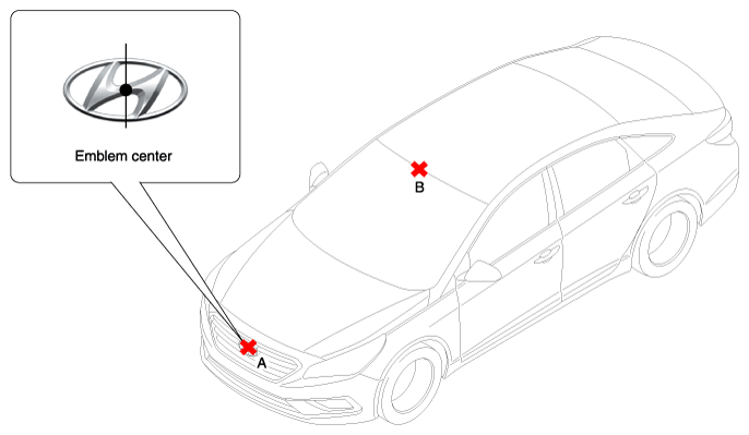
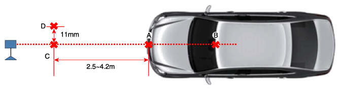
- Mark the center point of emblem (A) and the center point on top of wind glass (B).
 Courtesy of HYUNDAI MOTOR AMERICA
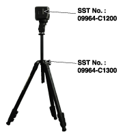
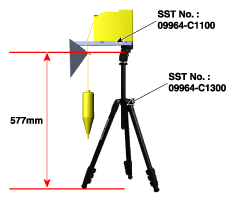
- Connect the ASCC Calibration beam (SST No.: 09964-C1200) to the Tri-Pod (SST No.: 09964-C1300).
 Courtesy of HYUNDAI MOTOR AMERICA
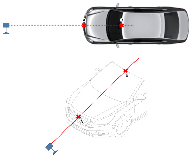
- Match the vertical line of laser to (A) and (B) using the ASCC calibration beam pointer.
 Courtesy of HYUNDAI MOTOR AMERICA
- Mark (C) located in 2.5~4.2 m from (A) in front of the vehicle.
- Mark (D) at the place which is 11 mm away from (C) to the left in vertical direction.
 Courtesy of HYUNDAI MOTOR AMERICA
- Disconnect the ASCC Calibration beam (SST No.: 09964-C1200) from the Tri-Pod (SST No.: 09964-C1300).
- Connect the reflector (SST No.: 09964-C1100) to the tripod (SST No.: 09964-C1300) and set the reflector center height to 577 mm.
 Courtesy of HYUNDAI MOTOR AMERICA
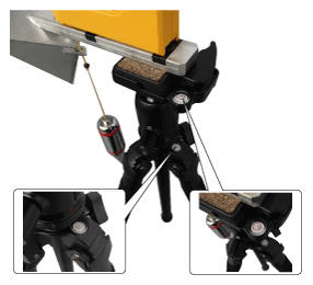
- Set the reflector horizontal using the leveler which is built in the tripod (SST No.: 09964-C1300).
 Courtesy of HYUNDAI MOTOR AMERICA
NOTE:
Balance the level so that the bubble in the level is set between the spec lines.
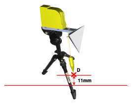
- Set SST (reflector or tripod) to match the position of SST (reflector) to the position of (D).
 Courtesy of HYUNDAI MOTOR AMERICA
NOTE:
Visually check that the reflecting side of the reflector is levelled with the front of the vehicle.
- Check again the radar sensor and the surface of front bumper for the following parts with the eyes.
NOTE:
- Make sure that there is no debris, or reflecting object on the surface of the radar.
- Make sure that there is no debris, or reflecting object on the radiator grill.
- Connect the GDS to the DLC of the vehicle and start sensor alignment.
NOTE:
If the engine is running, the vibration may cause inaccurate sensor alignment, so perform sensor alignment in IG ON mode.
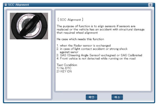
- After correctly selecting the vehicle model, select "SCC Alignment" from the auxiliary functions in GDS Menu.
 Courtesy of HYUNDAI MOTOR AMERICA
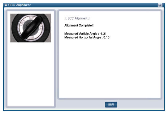
- Perform sensor alignment by following the directions in the GDS monitor.
 Courtesy of HYUNDAI MOTOR AMERICA
- In case of sensor alignment failure, check the alignment conditions. Turn the ignition key OFF, then reperform the sensor alignment procedure.