October 30: LEMON manuals on a temporary server, it is slow and having issues, download the manuals you need! Later in November we will switch back to the fast server.
Sensor Range Charts
Sensor operating range information can help determine if a sensor is out of calibration. An out-of-calibration sensor may not set a trouble code, but it may cause driveability problems.
NOTE:
Unless stated otherwise in test procedure, perform all voltage tests using a Digital Volt-Ohmmeter (DVOM) with a minimum 10-megohm input impedance.
COOLANT TEMPERATURE SENSOR RESISTANCE
| Temperature - °F (°C) |
Ohms |
| 68 (20) |
2100-2900 |
| 122 (50) |
680-1000 |
| 176 (80) |
300-330 |
EGR TEMPERATURE SENSOR RESISTANCE
| Temperature - °F (°C) |
Ohms |
| 212 (100) |
76,770-93,830 |
FUEL TEMPERATURE SENSOR RESISTANCE (M30 & Q45)
| Temperature - °F (°C) |
Ohms |
| 68 (20) |
2100-2900 |
| 122 (50) |
680-1000 |
| 176 (80) |
300-330 |
HEATED OXYGEN SENSOR VOLTAGE
| Condition |
Volts |
| Lean |
0-0.3 |
| Rich |
0.6-1.0 |
CLOSED & WIDE OPEN THROTTLE SWITCH CONTINUITY
(G20)
| Position |
Reading |
| Closed Throttle |
Blue/Orange & White Green |
| Wide Open Throttle |
Blue/Orange & Blue Red |
CLOSED THROTTLE POSITION SWITCH CONTINUITY (J30 & Q45)
| Position |
Reading |
| Closed Throttle |
Continuity |
| Open Throttle |
No Continuity |
THROTTLE POSITION SENSOR RESISTANCE
| Position |
Ohms |
| G20 |
| Closed Throttle |
2000 |
| Partially Open |
2000-10,000 |
| Wide Open Throttle |
10,000 |
| J30 |
| Closed Throttle |
1700 |
| Partially Open |
1700-10500 |
| Wide Open Throttle |
10500 |
| Q45 |
| Closed Throttle |
700 |
| Partially Open |
700-5000 |
| Wide Open Throttle |
5000 |
MASS AIRFLOW SENSOR VOLTAGE (LOW RPM)
| Application |
Terminal No |
Volts |
| G20 |
"A" |
1.3-1.7 |
| J30 |
"B" |
1.0-1.4 |
| Q45 |
"1" |
1.0-1.4 |
MASS AIRFLOW SENSOR VOLTAGE (HIGH RPM)
| Application |
Terminal No |
Volts |
| G20 |
"A" |
1.7-2.1 |
| J30 |
"B" |
1.4-1.9 |
| Q45 |
"1" |
1.4-1.9 |
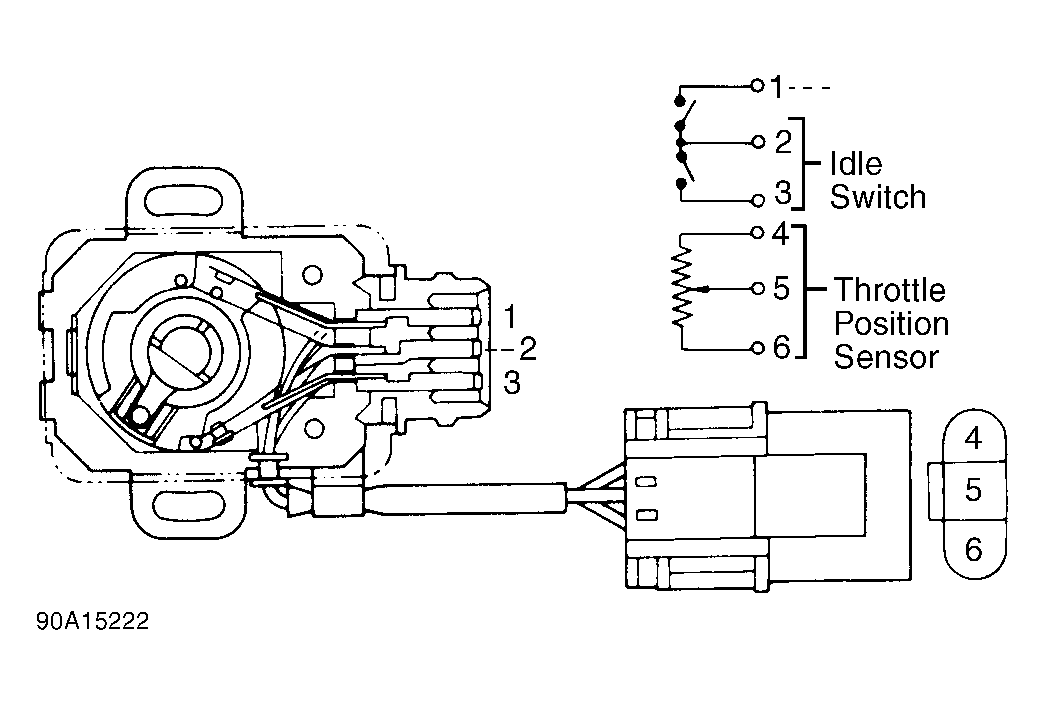 Courtesy of NISSAN MOTOR CO., U.S.A.