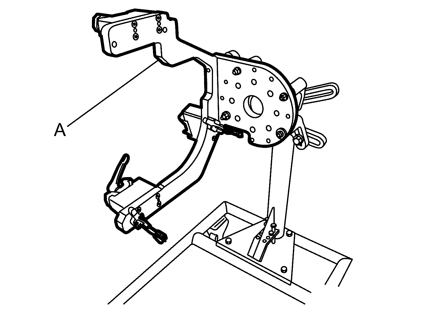
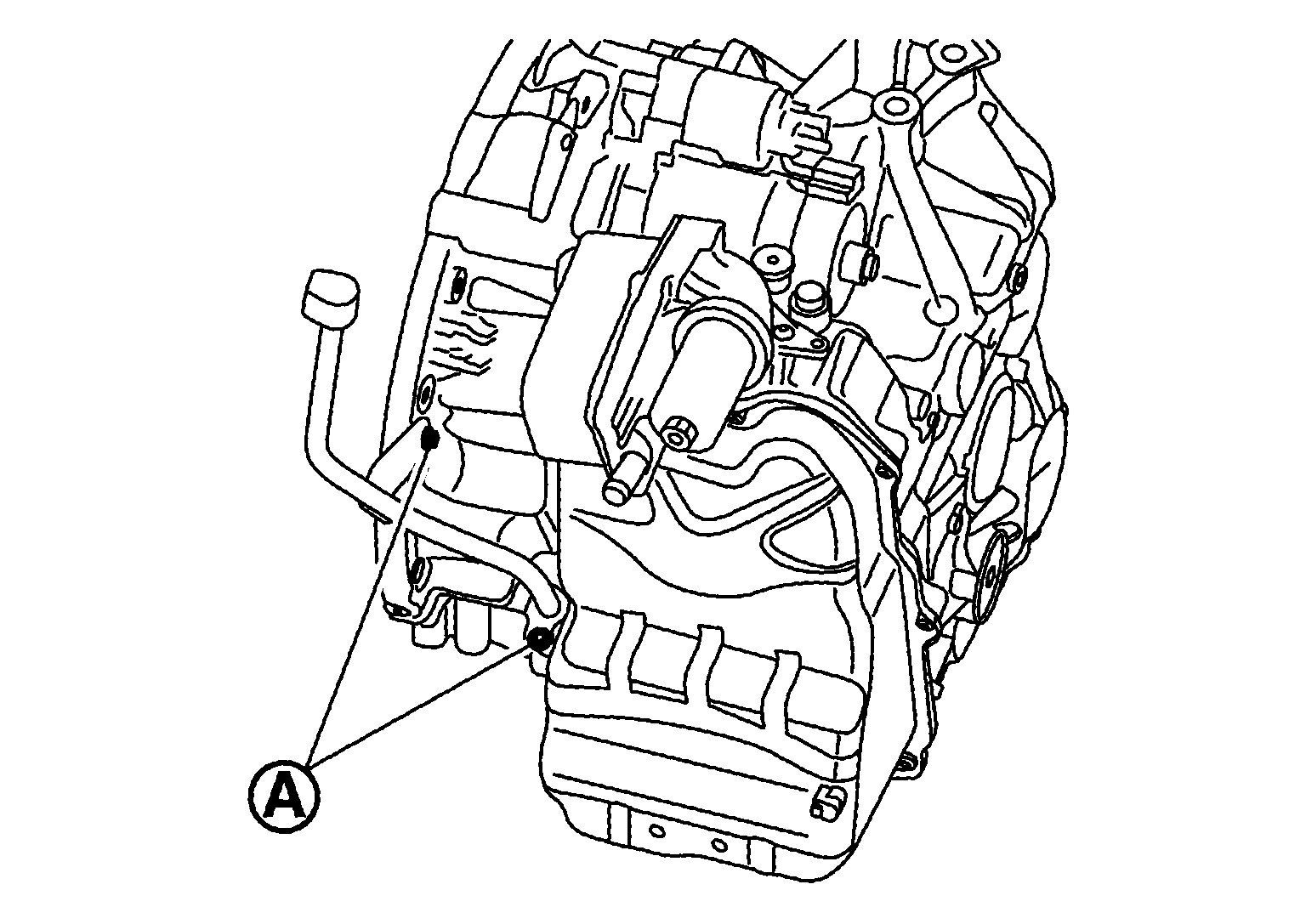
- Install assembly device (A) [SST: KV315H0460 (TechMate No. -) (DAIMLER tool No. 724 589 00 40 00)] to engine stand.
 Courtesy of NISSAN NORTH AMERICA, INC. Courtesy of NISSAN NORTH AMERICA, INC.
|
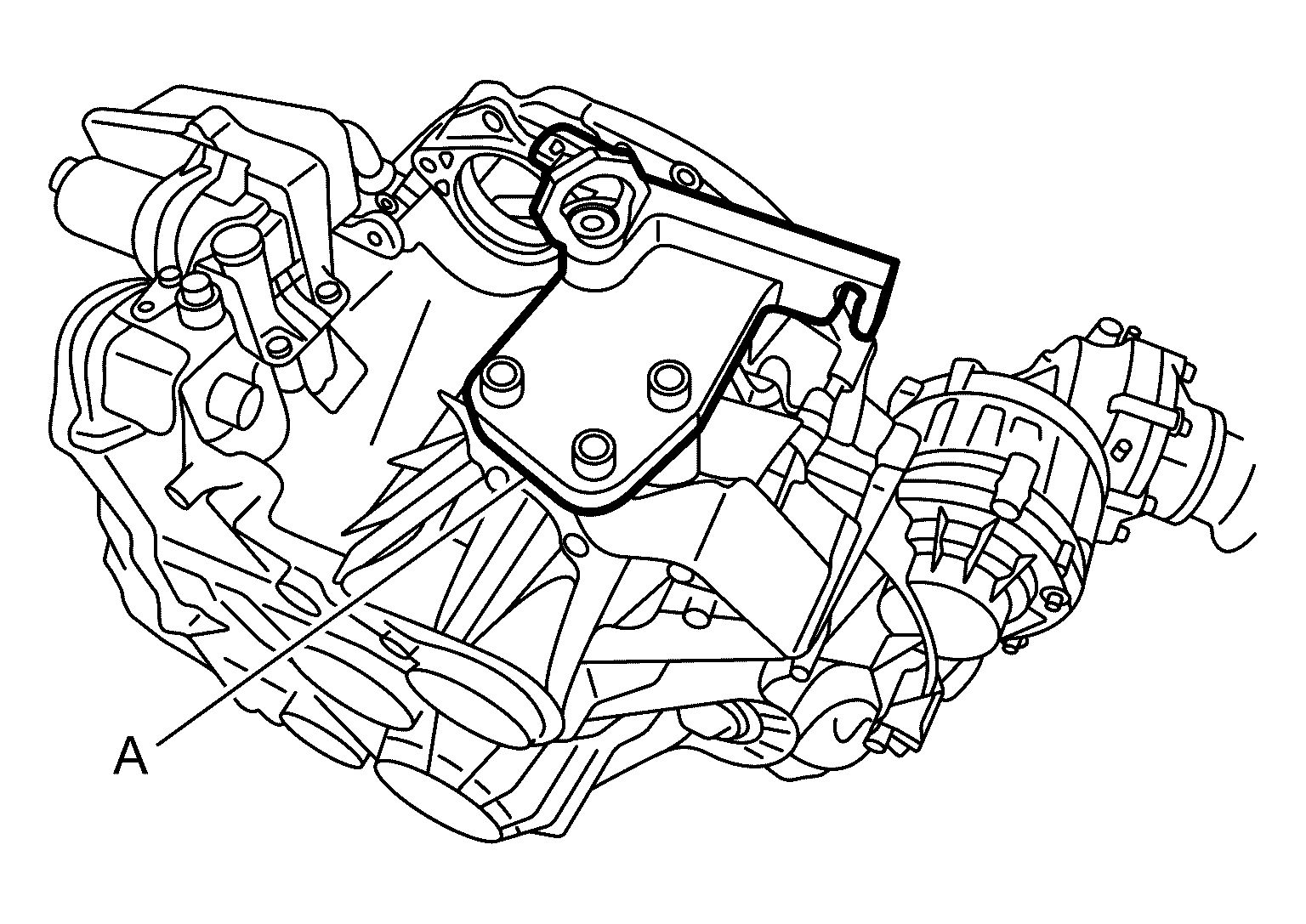
- Remove housing carrier (A) from assembly device and install to transaxle.
 Courtesy of NISSAN NORTH AMERICA, INC. Courtesy of NISSAN NORTH AMERICA, INC.
|
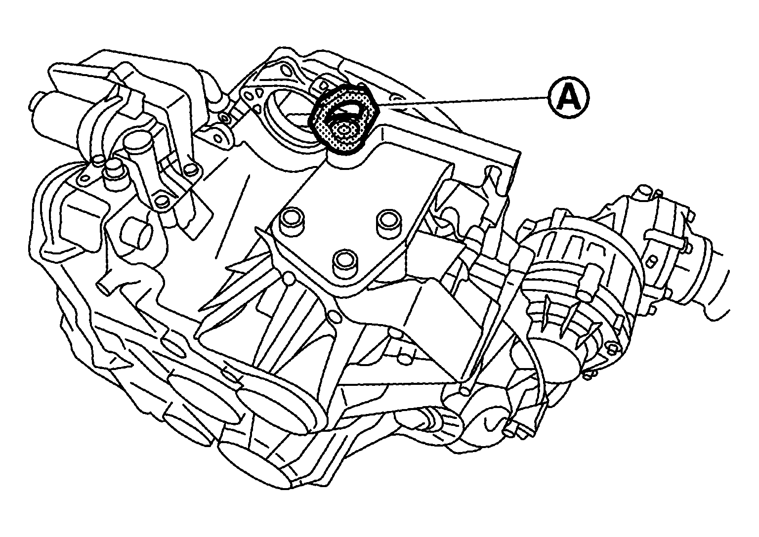
- Connect hoist to the hole of
 and lift transaxle.
 Courtesy of NISSAN NORTH AMERICA, INC. Courtesy of NISSAN NORTH AMERICA, INC.
|
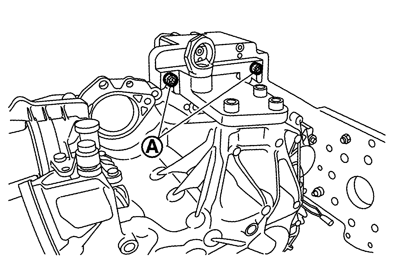
- Tighten bolt
and install transaxle to assembly device.
 Courtesy of NISSAN NORTH AMERICA, INC. Courtesy of NISSAN NORTH AMERICA, INC.
|
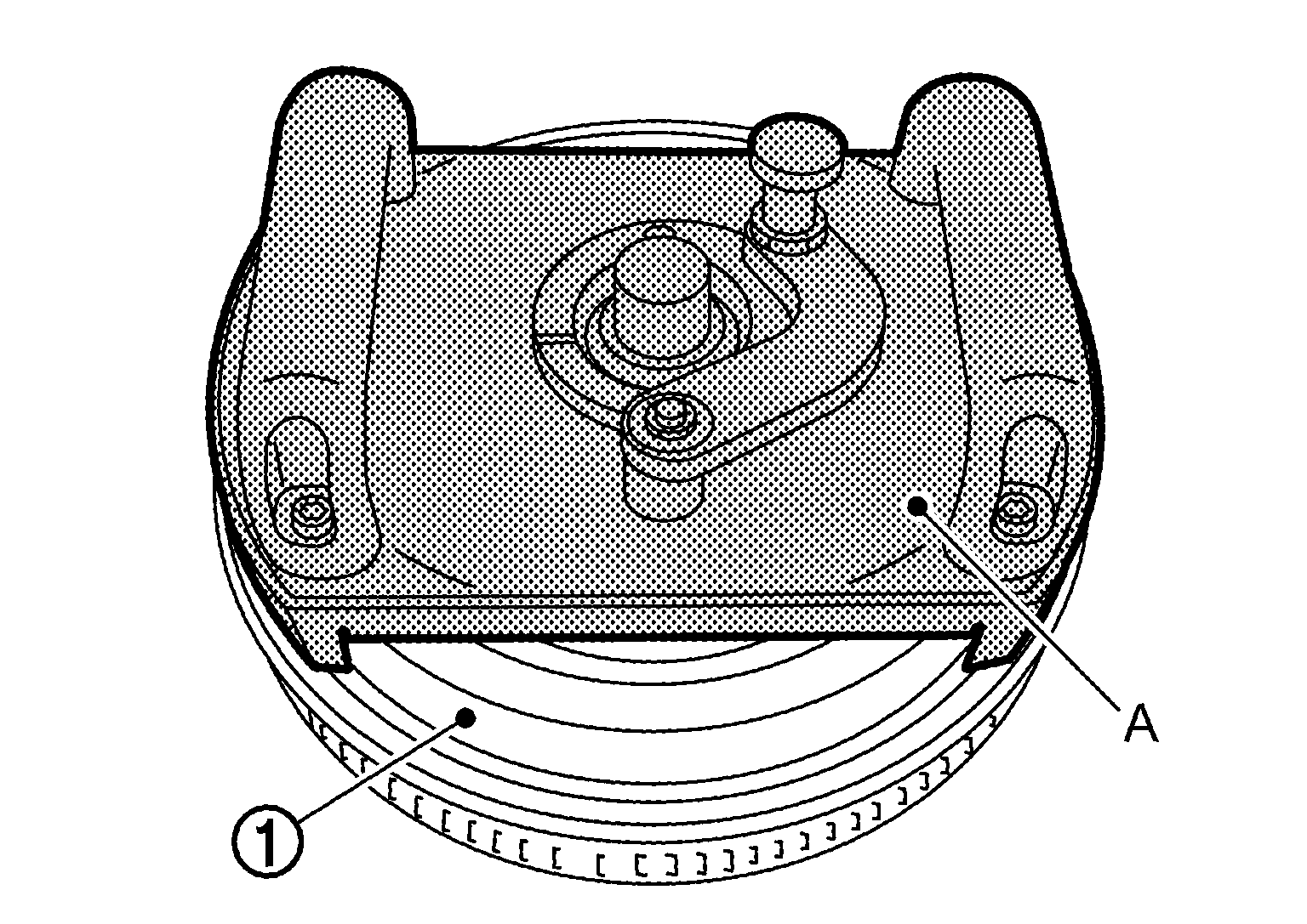
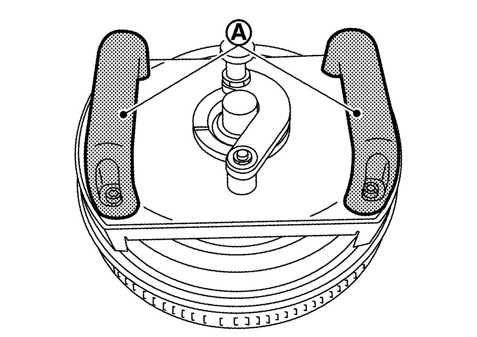
- Vertically position lever (A) of assembly device and allow transaxle case to firmly contact with assembly device.
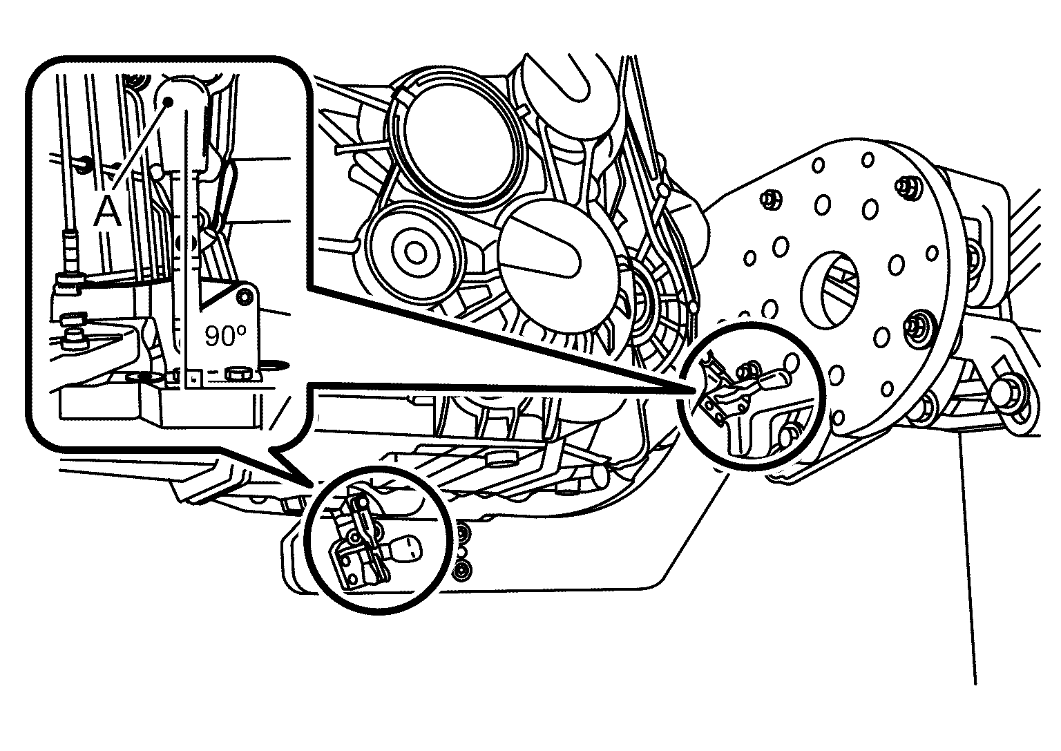 Courtesy of NISSAN NORTH AMERICA, INC. Courtesy of NISSAN NORTH AMERICA, INC.
|
CAUTION:
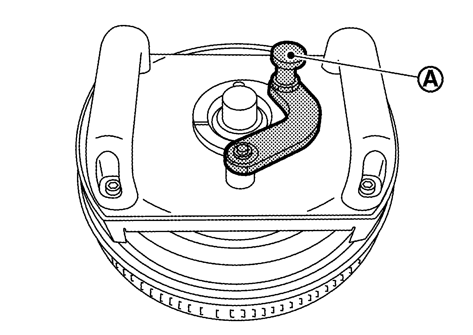
- Push (A) in the direction shown by arrow and check that lever cannot be moved.
 Courtesy of NISSAN NORTH AMERICA, INC. Courtesy of NISSAN NORTH AMERICA, INC.
|
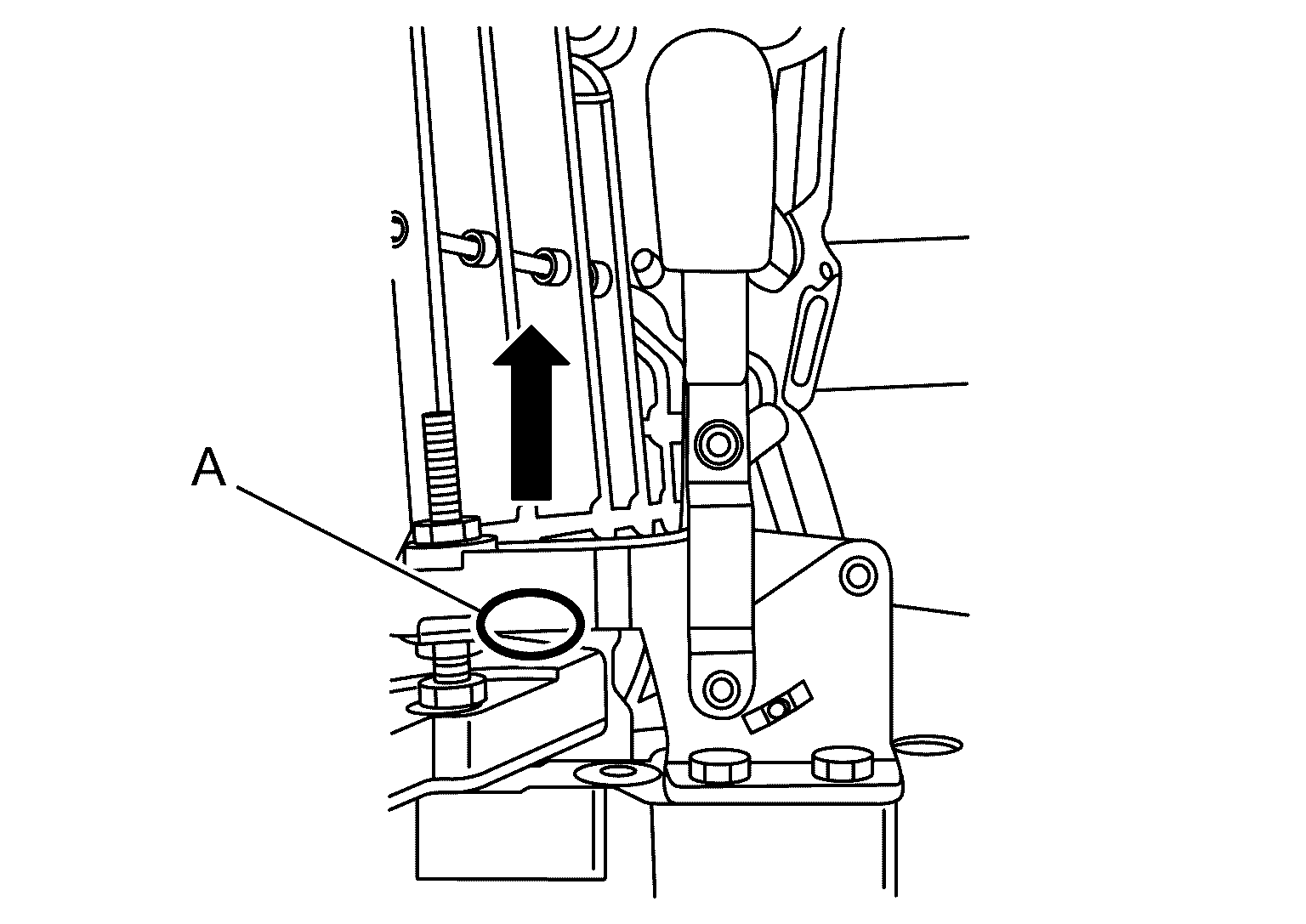
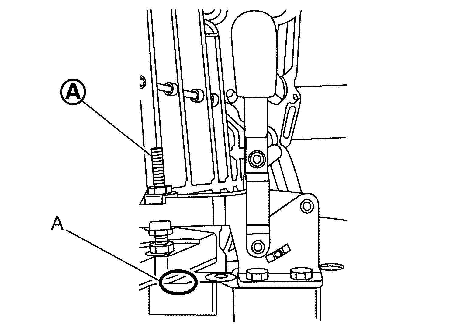
- If the lever cannot be positioned vertically under the condition that no clearance exists between transaxle case and assembly device (A), adjust bolt position of
the lever vertically.
 Courtesy of NISSAN NORTH AMERICA, INC. Courtesy of NISSAN NORTH AMERICA, INC.
|
- If the lever cannot be positioned vertically under the condition that some clearance exists between transaxle case and assembly device, eliminate the clearance between transaxle case and assembly device by rotating engine stand to position the lever vertically.
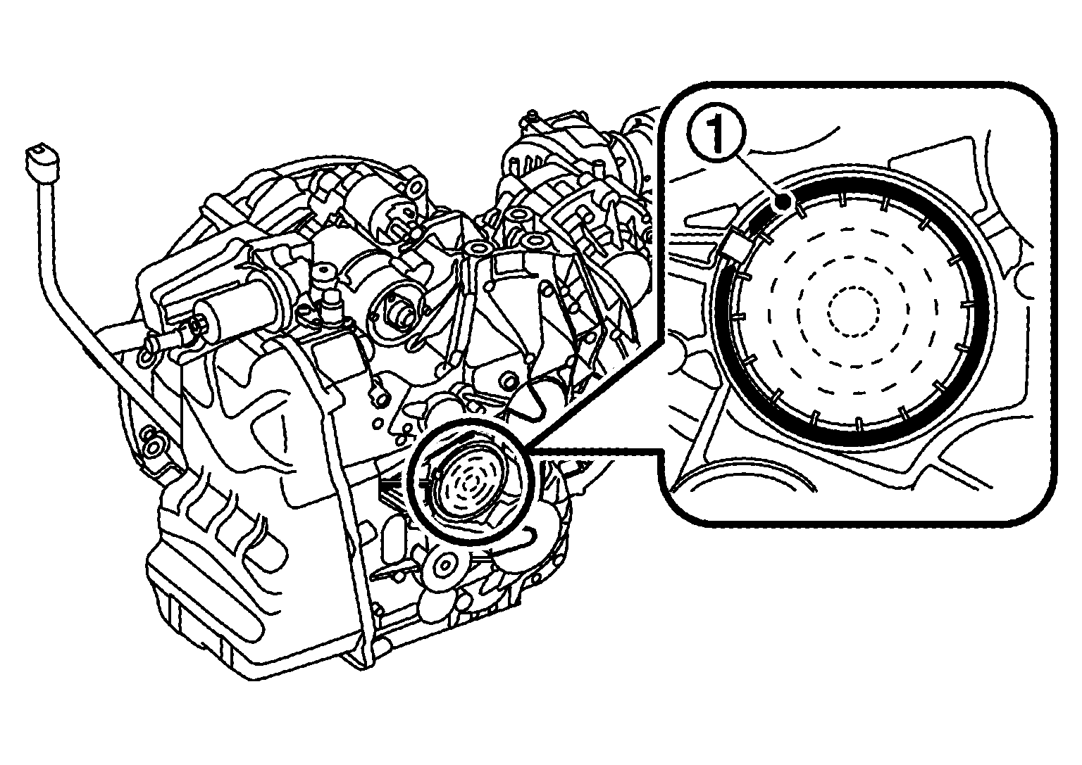
- Insert an appropriate tool into
of snap ring to remove snap ring.
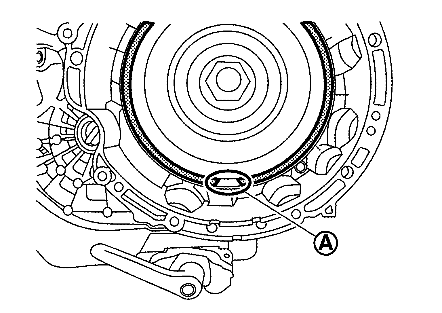 Courtesy of NISSAN NORTH AMERICA, INC. Courtesy of NISSAN NORTH AMERICA, INC.
|
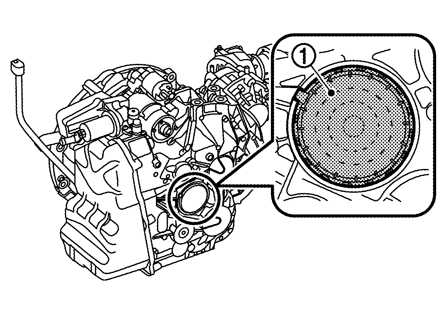
- Remove cover by using a suitable tool.
CAUTION:
Never reuse cover.
- Install assembly tool (A) [SST: KV315H0440 (TechMate No. -) (DAIMLER tool No. 724 589 00 31 00)] to dual clutch
 .
.
 Courtesy of NISSAN NORTH AMERICA, INC. Courtesy of NISSAN NORTH AMERICA, INC.
|
CAUTION:
The periphery of dual clutch is sharp. Be careful not to touch it.
- Pull lever
in the vertical direction to release the lock.
 Courtesy of NISSAN NORTH AMERICA, INC. Courtesy of NISSAN NORTH AMERICA, INC.
|
CAUTION:
The periphery of dual clutch is sharp. Be careful not to touch it.
- Move lever
in the direction shown by arrow and engage the tip of lever with hole
 .
.
 Courtesy of NISSAN NORTH AMERICA, INC. Courtesy of NISSAN NORTH AMERICA, INC.
|
CAUTION:
The periphery of dual clutch is sharp. Be careful not to touch it.
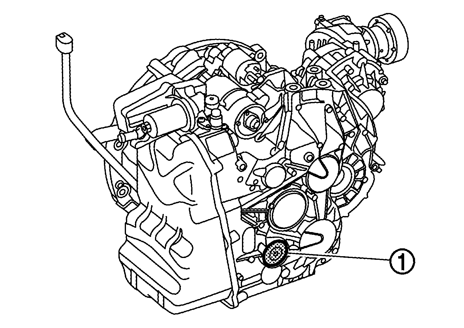
- Hold
and remove dual clutch from the transaxle.
 Courtesy of NISSAN NORTH AMERICA, INC. Courtesy of NISSAN NORTH AMERICA, INC.
|
CAUTION:
The periphery of dual clutch is sharp. Be careful not to touch it.
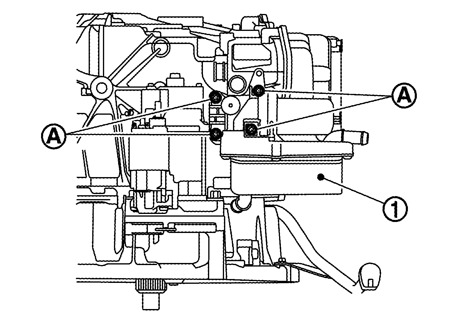
- Remove transmission cooling module mounting bolts
.
 Courtesy of NISSAN NORTH AMERICA, INC. Courtesy of NISSAN NORTH AMERICA, INC.
|
- Remove transmission cooling module
.
- Remove transfer assembly. Refer to Removal and Installation
. (For AWD models)
- Remove snap ring
.
 Courtesy of NISSAN NORTH AMERICA, INC. Courtesy of NISSAN NORTH AMERICA, INC.
|
- Using suitable tool remove the cover with oil duct
.
 Courtesy of NISSAN NORTH AMERICA, INC. Courtesy of NISSAN NORTH AMERICA, INC.
|
CAUTION:
Never reuse cover with oil duct.
- Using suitable tool remove the cover
.
 Courtesy of NISSAN NORTH AMERICA, INC. Courtesy of NISSAN NORTH AMERICA, INC.
|
CAUTION:
Never reuse cover.
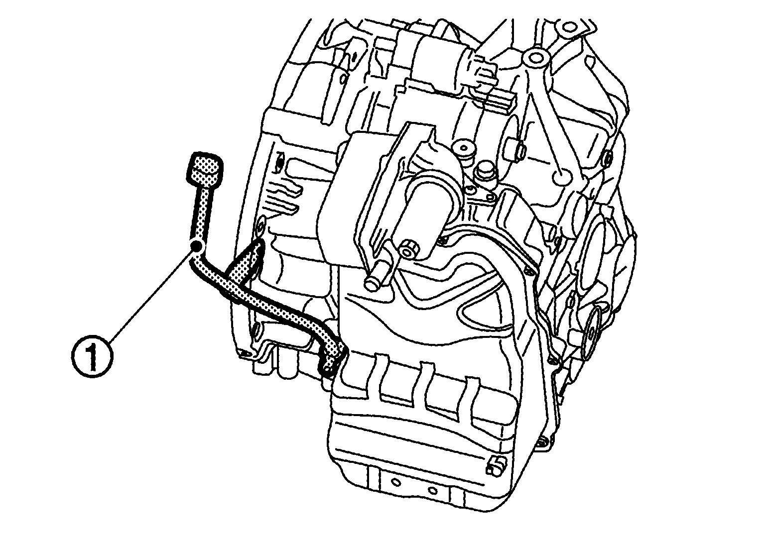
- Remove transaxle oil charging pipe mounting bolts
.
 Courtesy of NISSAN NORTH AMERICA, INC. Courtesy of NISSAN NORTH AMERICA, INC.
|
- Remove transaxle oil charging pipe
.
 Courtesy of NISSAN NORTH AMERICA, INC. Courtesy of NISSAN NORTH AMERICA, INC.
|
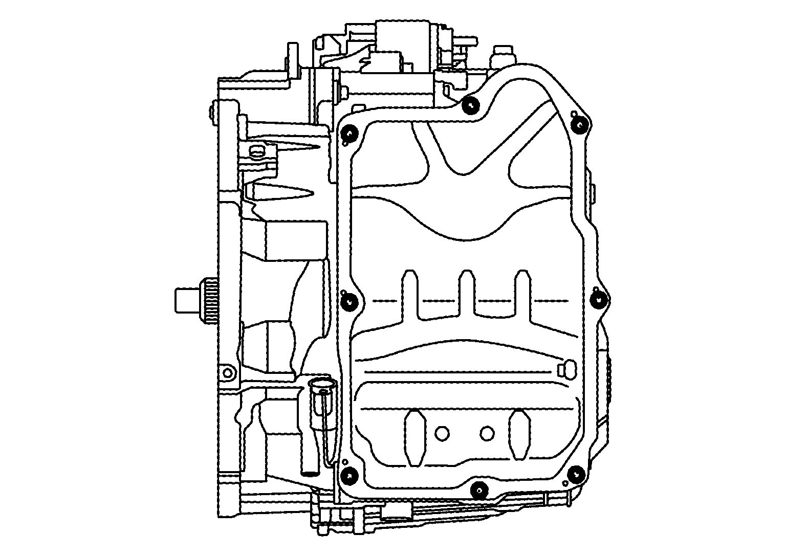
- Remove oil pan mounting bolts.
 Courtesy of NISSAN NORTH AMERICA, INC. Courtesy of NISSAN NORTH AMERICA, INC.
|
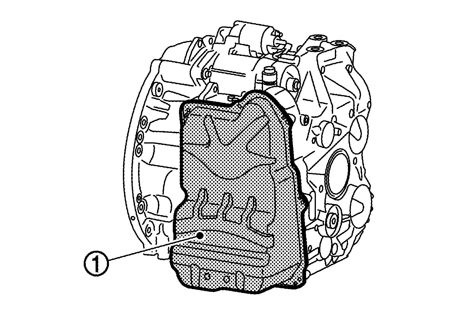
- Remove oil pan
.
 Courtesy of NISSAN NORTH AMERICA, INC. Courtesy of NISSAN NORTH AMERICA, INC.
|
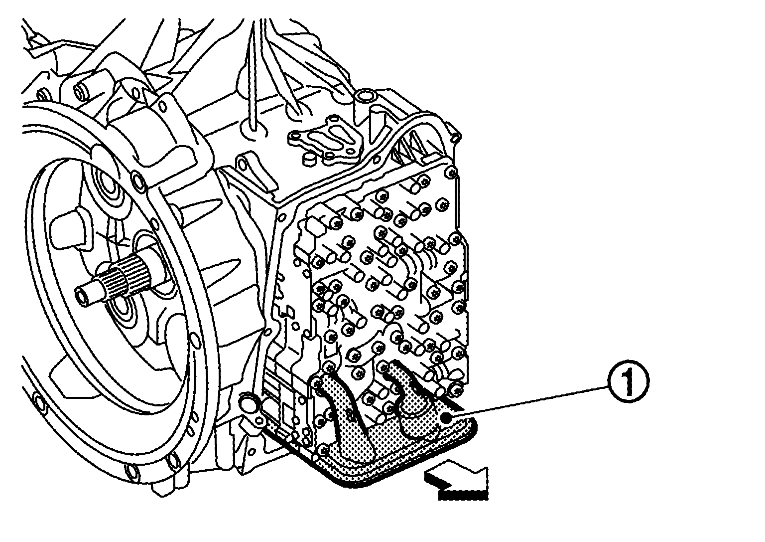
- Remove the oil filter
in the direction shown by arrow.
 Courtesy of NISSAN NORTH AMERICA, INC. Courtesy of NISSAN NORTH AMERICA, INC.
|
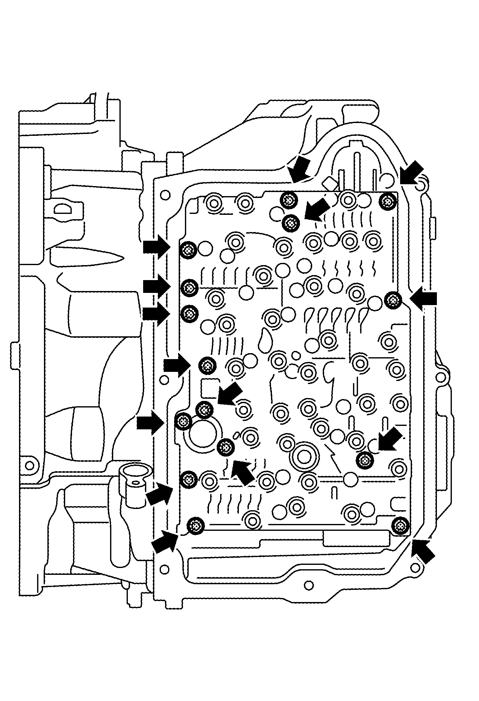
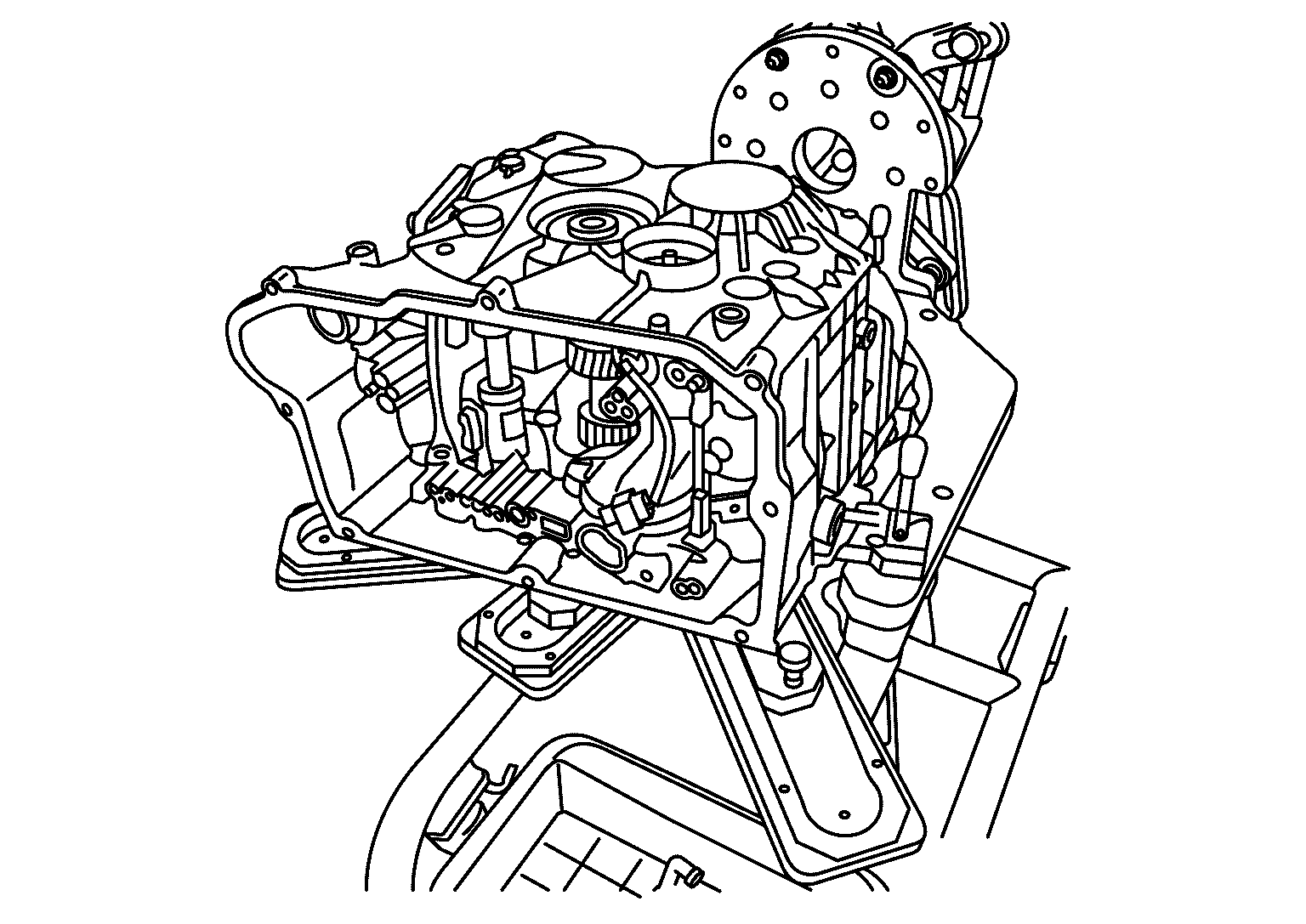
- Remove control valve mounting bolts.
 Courtesy of NISSAN NORTH AMERICA, INC. Courtesy of NISSAN NORTH AMERICA, INC.
|
- Disconnect the park pawl lift solenoid connector.
- Remove the control valve assembly
in the direction shown by arrow.
 Courtesy of NISSAN NORTH AMERICA, INC. Courtesy of NISSAN NORTH AMERICA, INC.
|
CAUTION:
Remove the control valve vertically without tilting, press and hold the
portion of TCM connector if necessary.
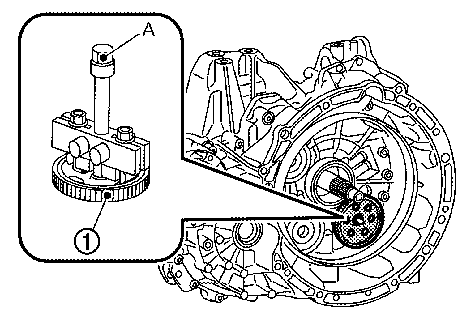
- Install the oil pump gear
using puller (A) [SST: KV315H0610 (TechMate No. -) (DAIMLER tool No. 724 589 02 33 00)] installed to the oil pump gear.
 Courtesy of NISSAN NORTH AMERICA, INC. Courtesy of NISSAN NORTH AMERICA, INC.
|
- Remove nut
.
 Courtesy of NISSAN NORTH AMERICA, INC. Courtesy of NISSAN NORTH AMERICA, INC.
|
NOTE:
Be careful that the nut is a left-hand thread.
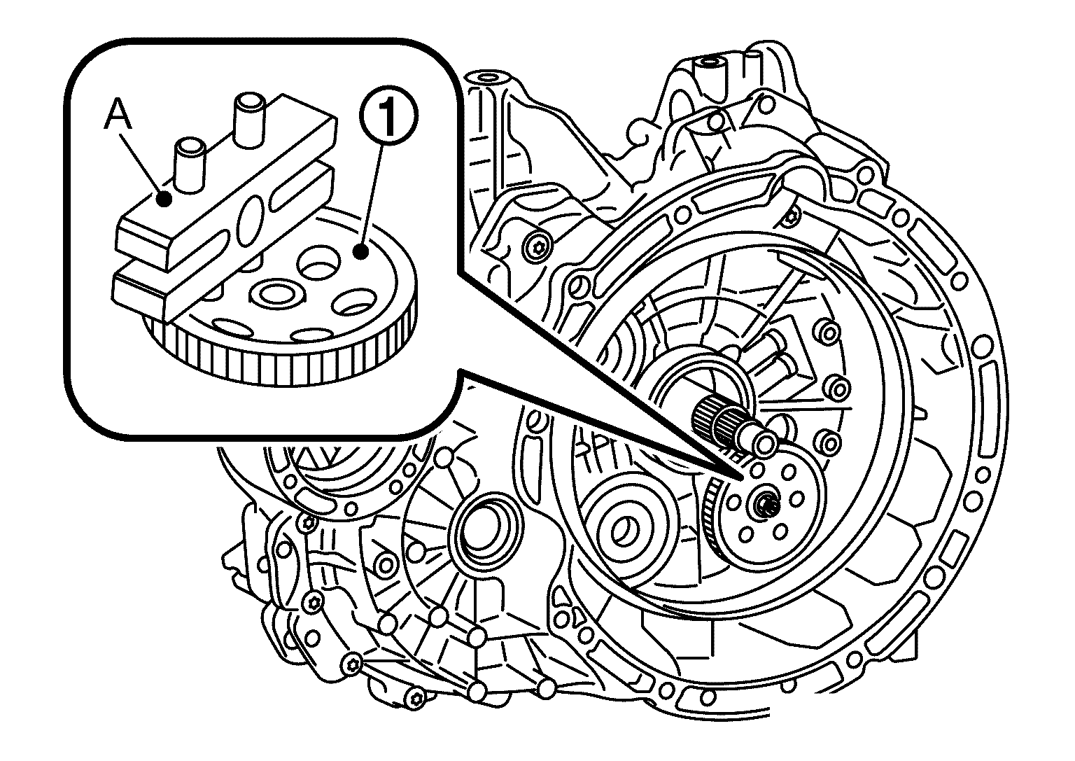
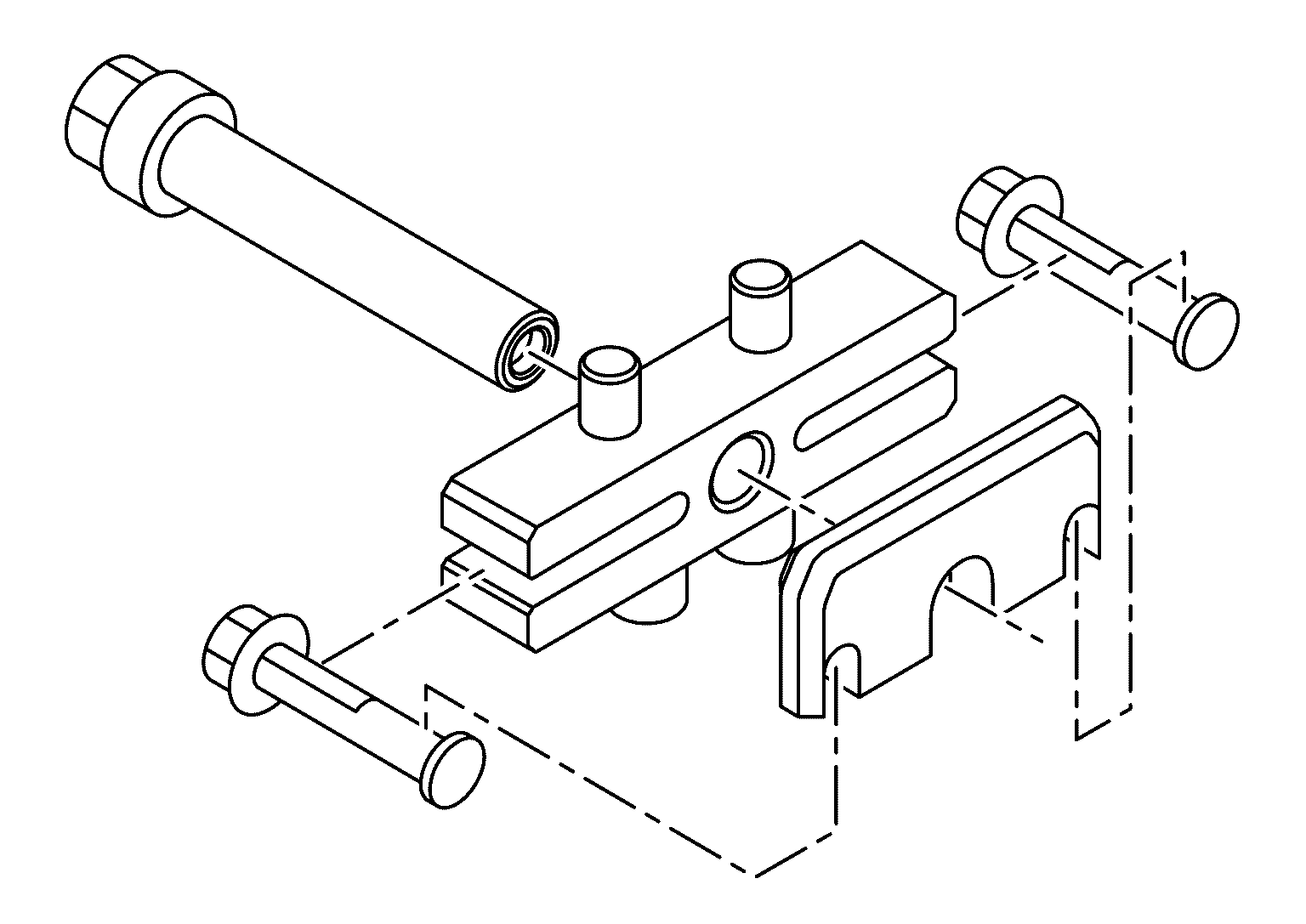
- Install puller (A) to the oil pump gear
.
 Courtesy of NISSAN NORTH AMERICA, INC. Courtesy of NISSAN NORTH AMERICA, INC.
|
NOTE:
Assemble puller as shown below
.
 Courtesy of NISSAN NORTH AMERICA, INC. Courtesy of NISSAN NORTH AMERICA, INC.
|
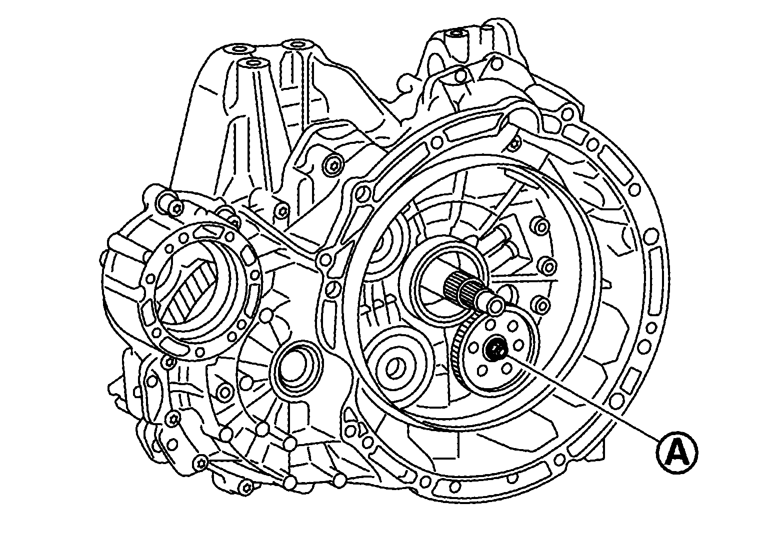
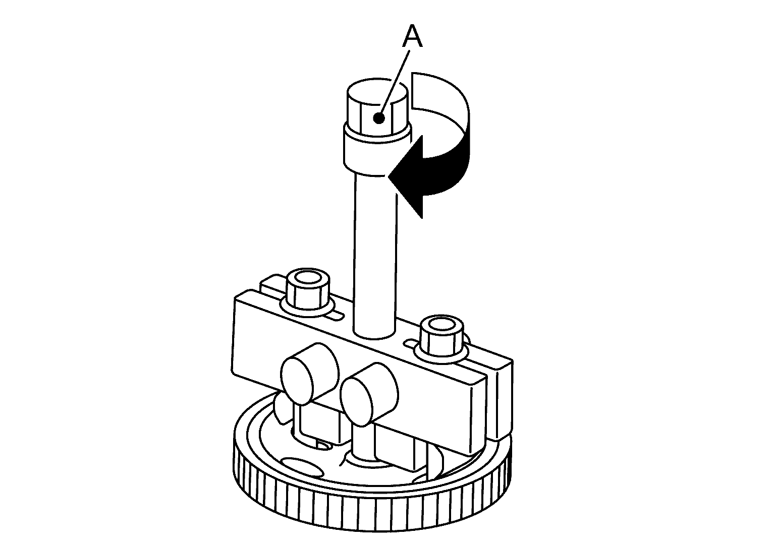
- Remove the oil pump gear by turning the spindle (A) of puller to the direction shown by figure.
 Courtesy of NISSAN NORTH AMERICA, INC. Courtesy of NISSAN NORTH AMERICA, INC.
|
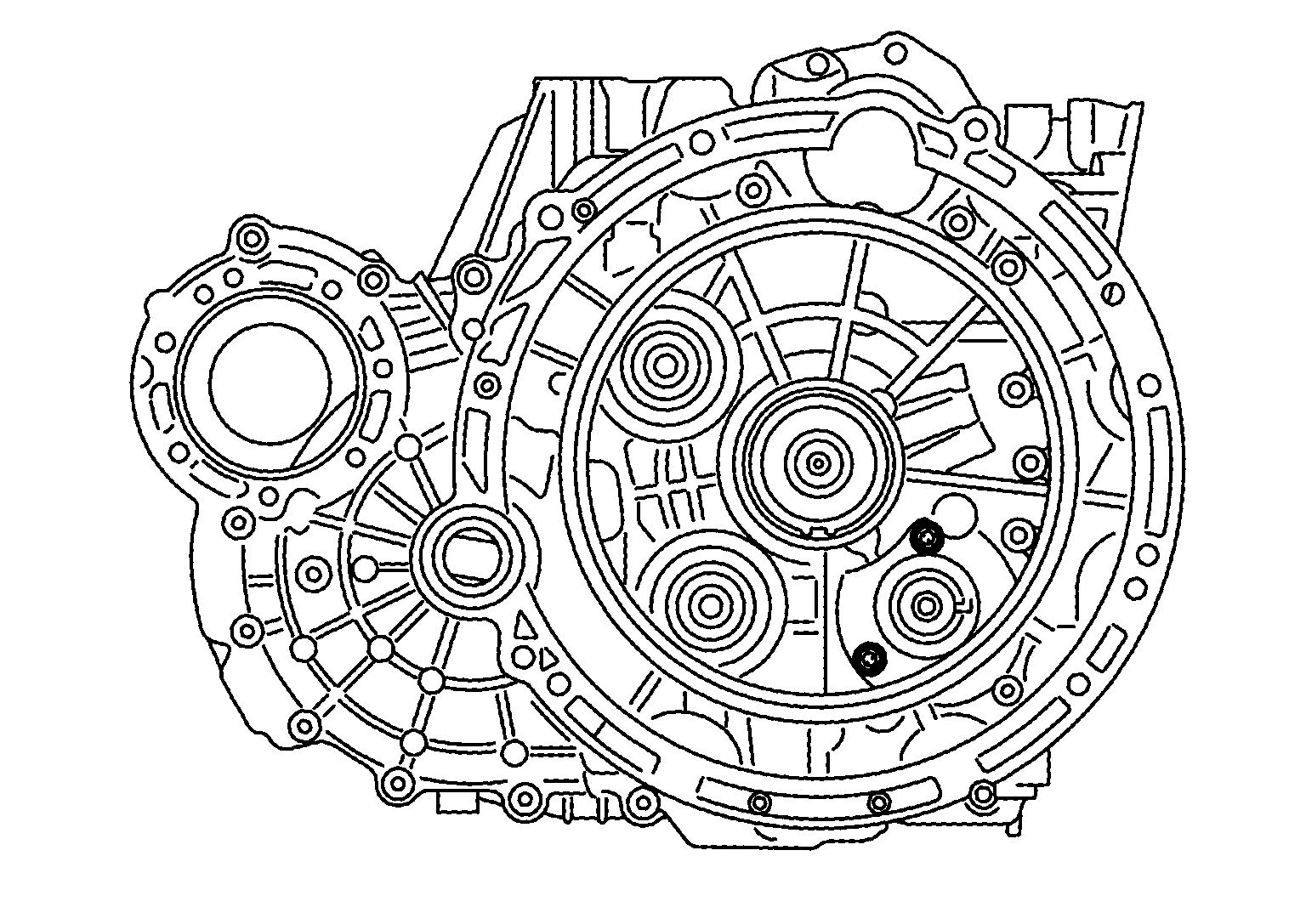
- Remove oil pump mounting bolts.
 Courtesy of NISSAN NORTH AMERICA, INC. Courtesy of NISSAN NORTH AMERICA, INC.
|
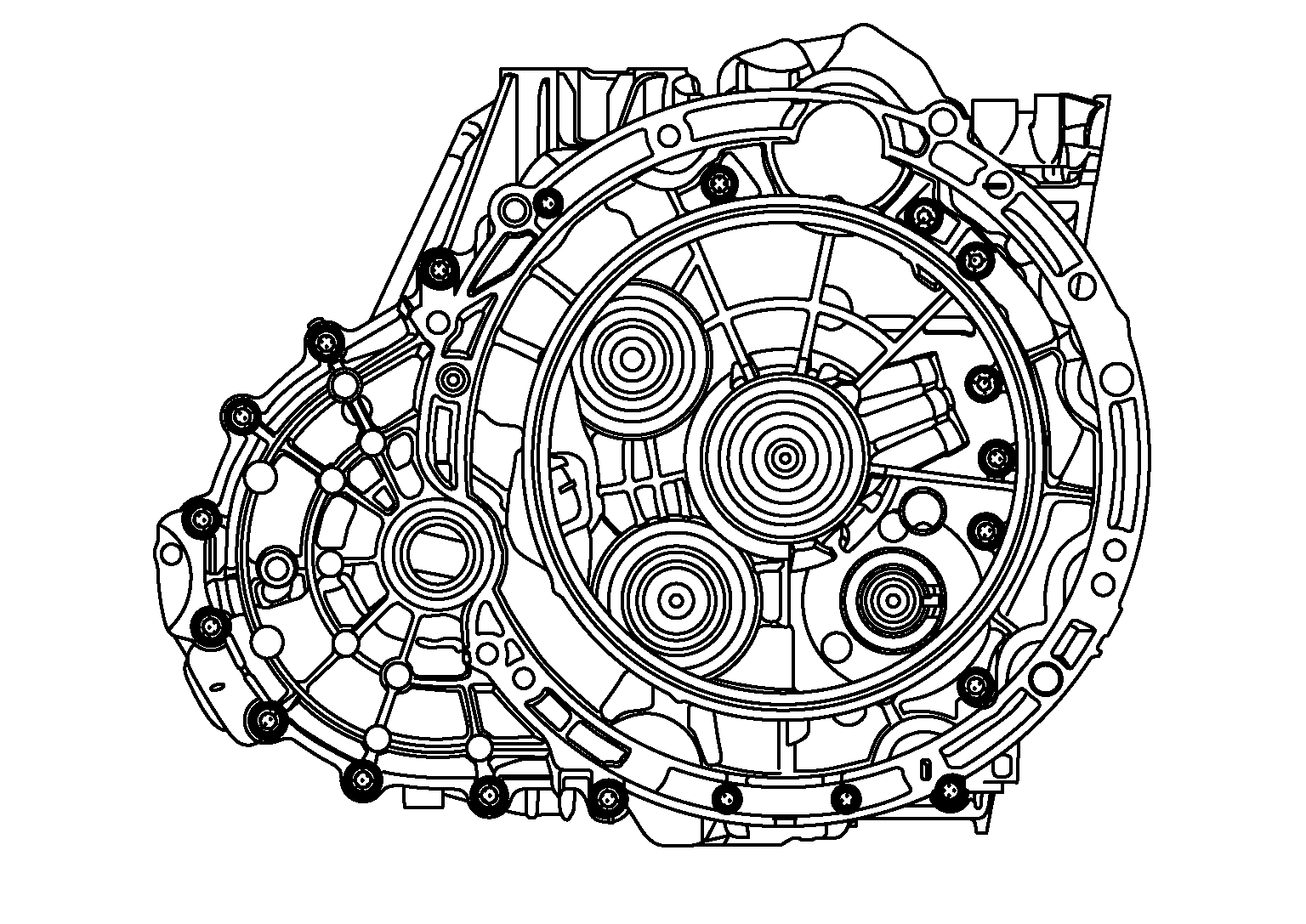
- Remove clutch housing mounting bolts.
- 2WD models
 Courtesy of NISSAN NORTH AMERICA, INC. Courtesy of NISSAN NORTH AMERICA, INC.
|
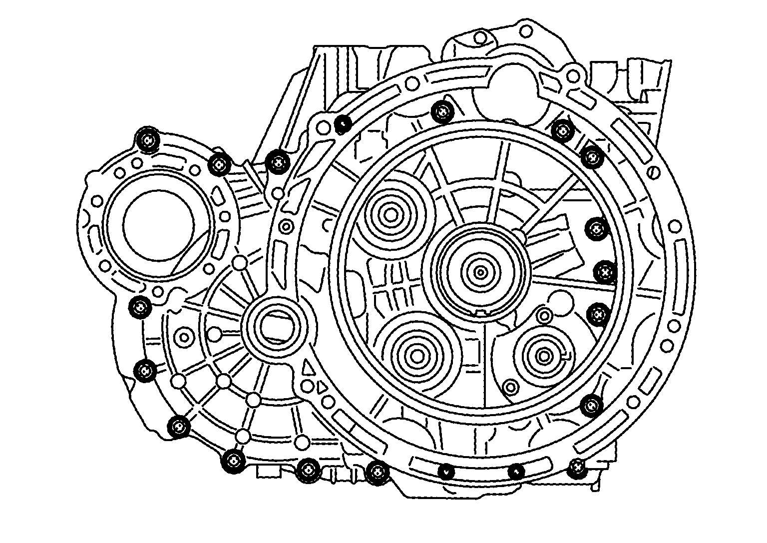
- AWD models
 Courtesy of NISSAN NORTH AMERICA, INC. Courtesy of NISSAN NORTH AMERICA, INC.
|
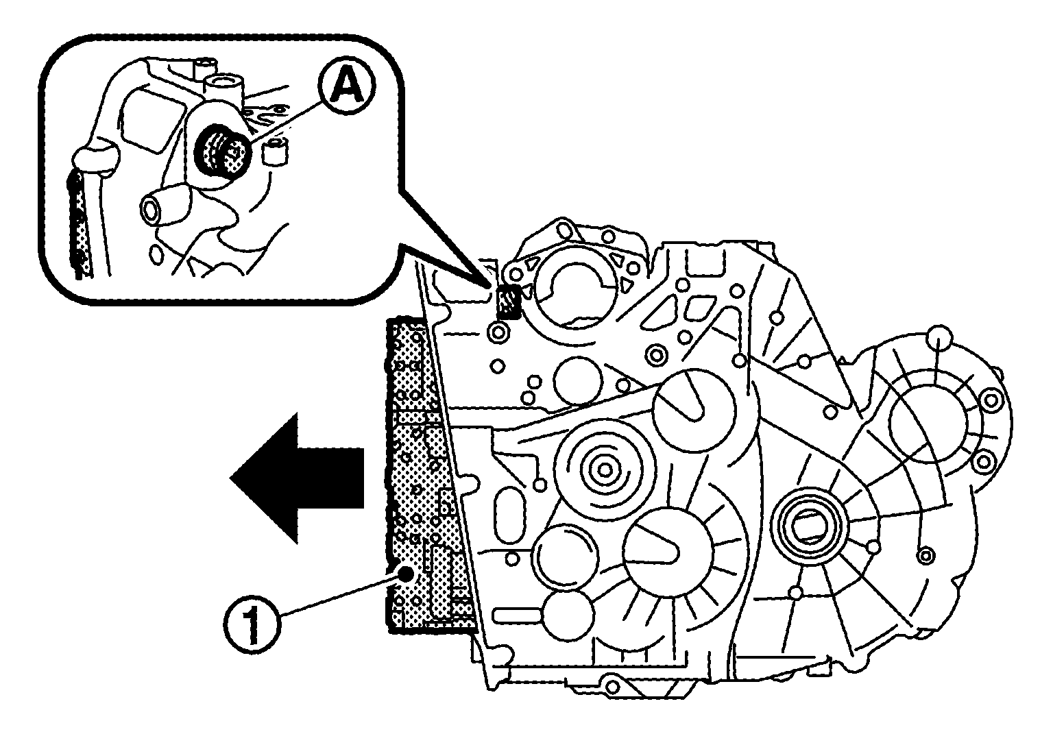
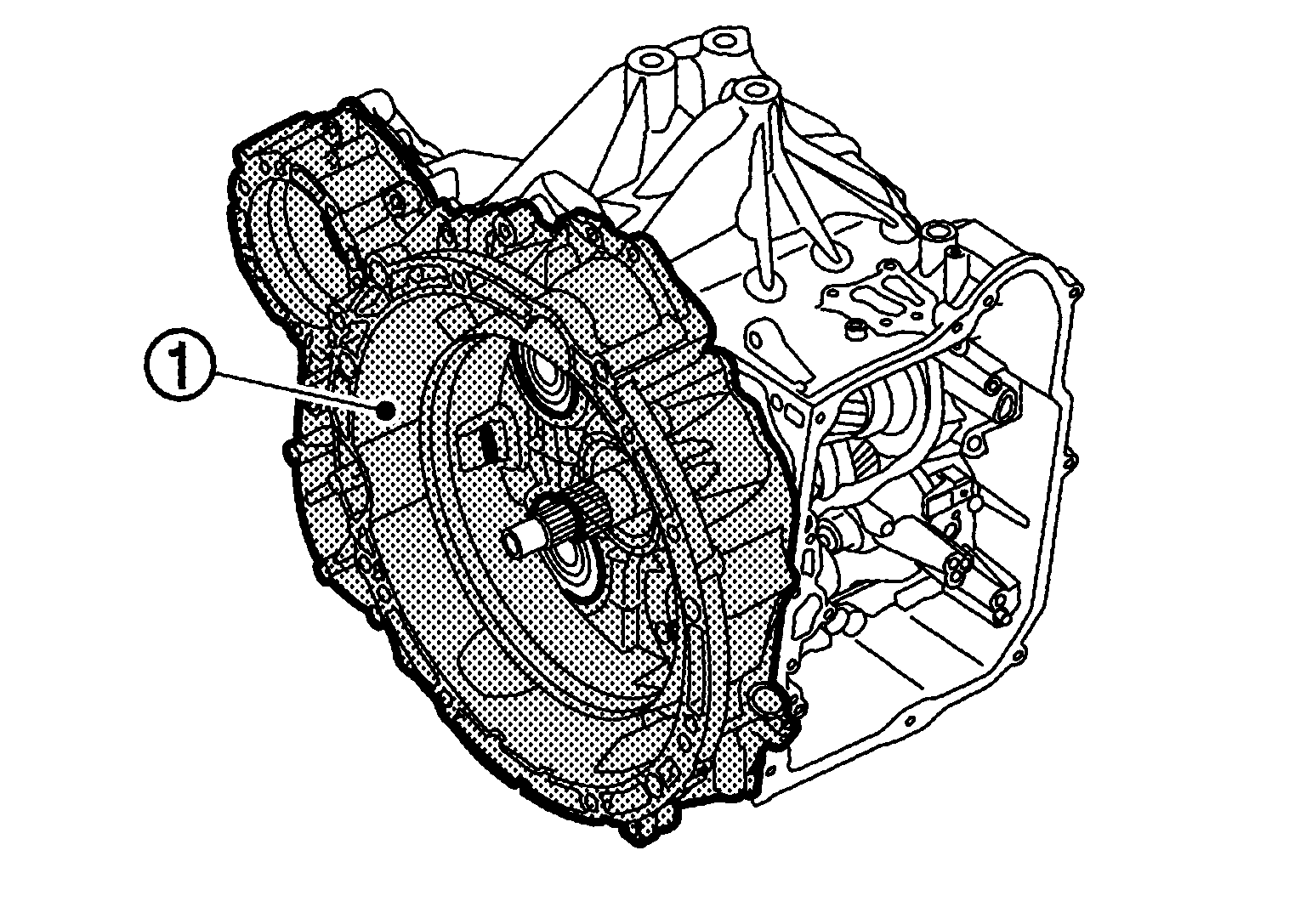
- Using suitable tool remove the clutch housing
.
 Courtesy of NISSAN NORTH AMERICA, INC. Courtesy of NISSAN NORTH AMERICA, INC.
|
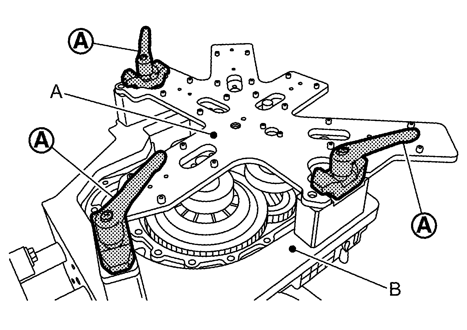
- Set assembly device (A) [SST: KV315H0540 (TechMate No. -) (DAIMLER tool No. 724 589 02 40 00)] on to assembly device (B) [SST: KV315H0460 (TechMate No. -) (DAIMLER tool No. 724 589 00 40 00)], then fasten the lever
to fix the assembly device (A).
 Courtesy of NISSAN NORTH AMERICA, INC. Courtesy of NISSAN NORTH AMERICA, INC.
|
- Turn the engine stand up to the position shown by figure.
 Courtesy of NISSAN NORTH AMERICA, INC. Courtesy of NISSAN NORTH AMERICA, INC.
|
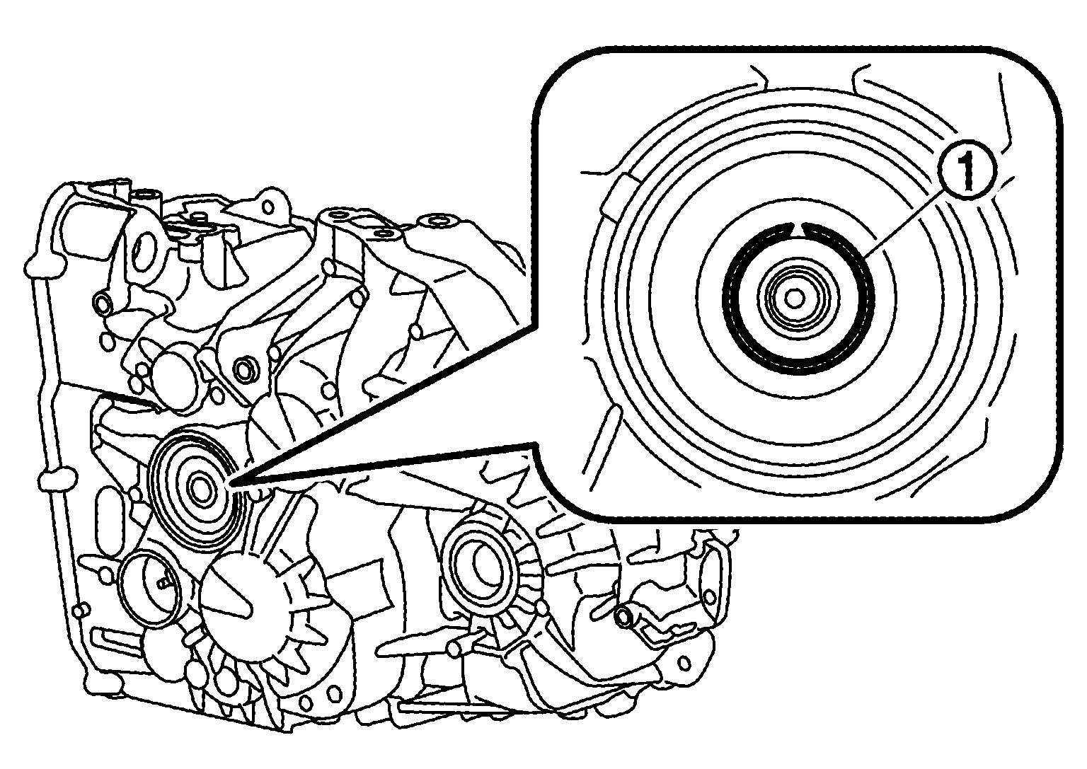
- Remove snap ring
.
 Courtesy of NISSAN NORTH AMERICA, INC. Courtesy of NISSAN NORTH AMERICA, INC.
|
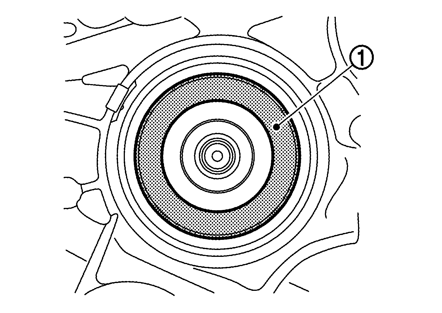
- Remove the dust washer
.
 Courtesy of NISSAN NORTH AMERICA, INC. Courtesy of NISSAN NORTH AMERICA, INC.
|
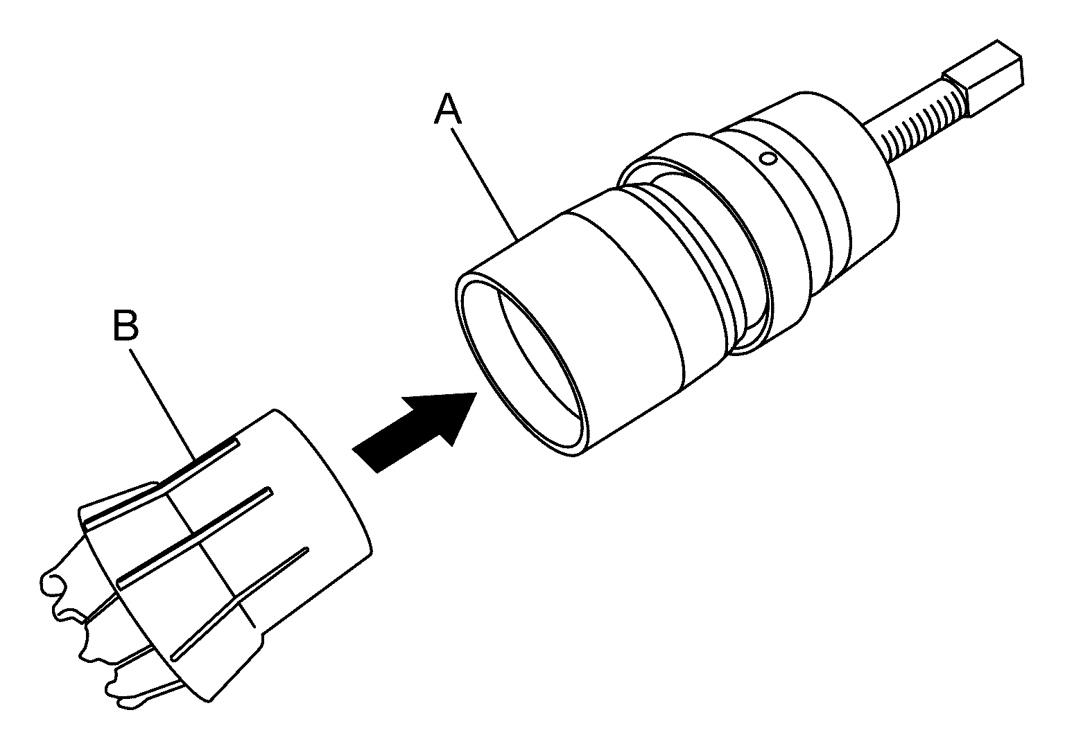
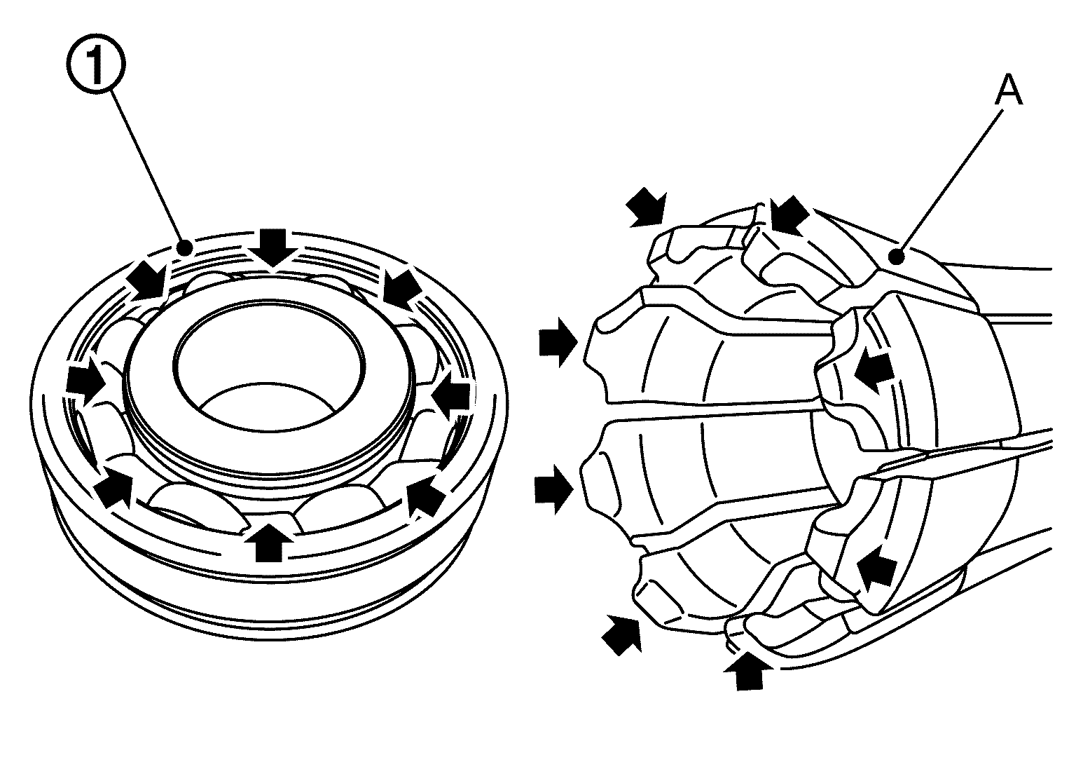
- Install collet chuck (B) [SST: KV325H0690 (TechMate No. -) (DAIMLER tool No. 168 589 00 34 00)] to puller (A) [SST: KV325H0050 (TechMate No. -) (DAIMLER tool No. 001 589 49 33 00)].
 Courtesy of NISSAN NORTH AMERICA, INC. Courtesy of NISSAN NORTH AMERICA, INC.
|
- Engage the tips of collet chuck (A) to ball bearing
.
 Courtesy of NISSAN NORTH AMERICA, INC. Courtesy of NISSAN NORTH AMERICA, INC.
|
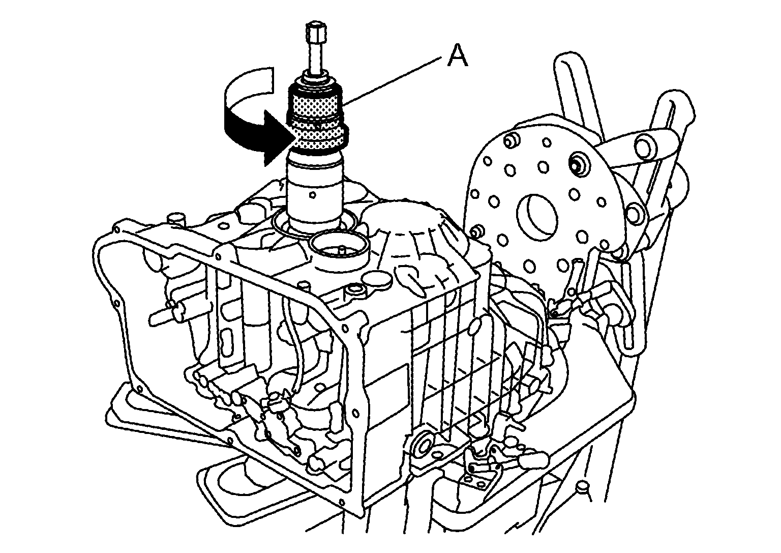
- Tighten the ball bearing with collet chuck by turning puller (A) to the direction shown by figure.
 Courtesy of NISSAN NORTH AMERICA, INC. Courtesy of NISSAN NORTH AMERICA, INC.
|
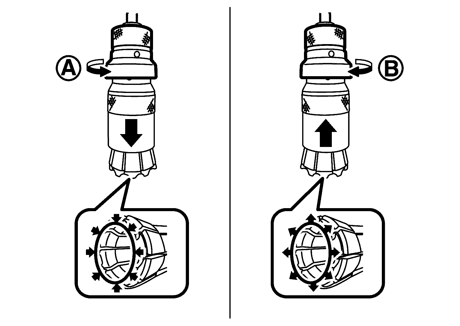
NOTE:
Collet chuck are tightened by turning puller to direction
, loosened by turning to direction
.
 Courtesy of NISSAN NORTH AMERICA, INC. Courtesy of NISSAN NORTH AMERICA, INC.
|
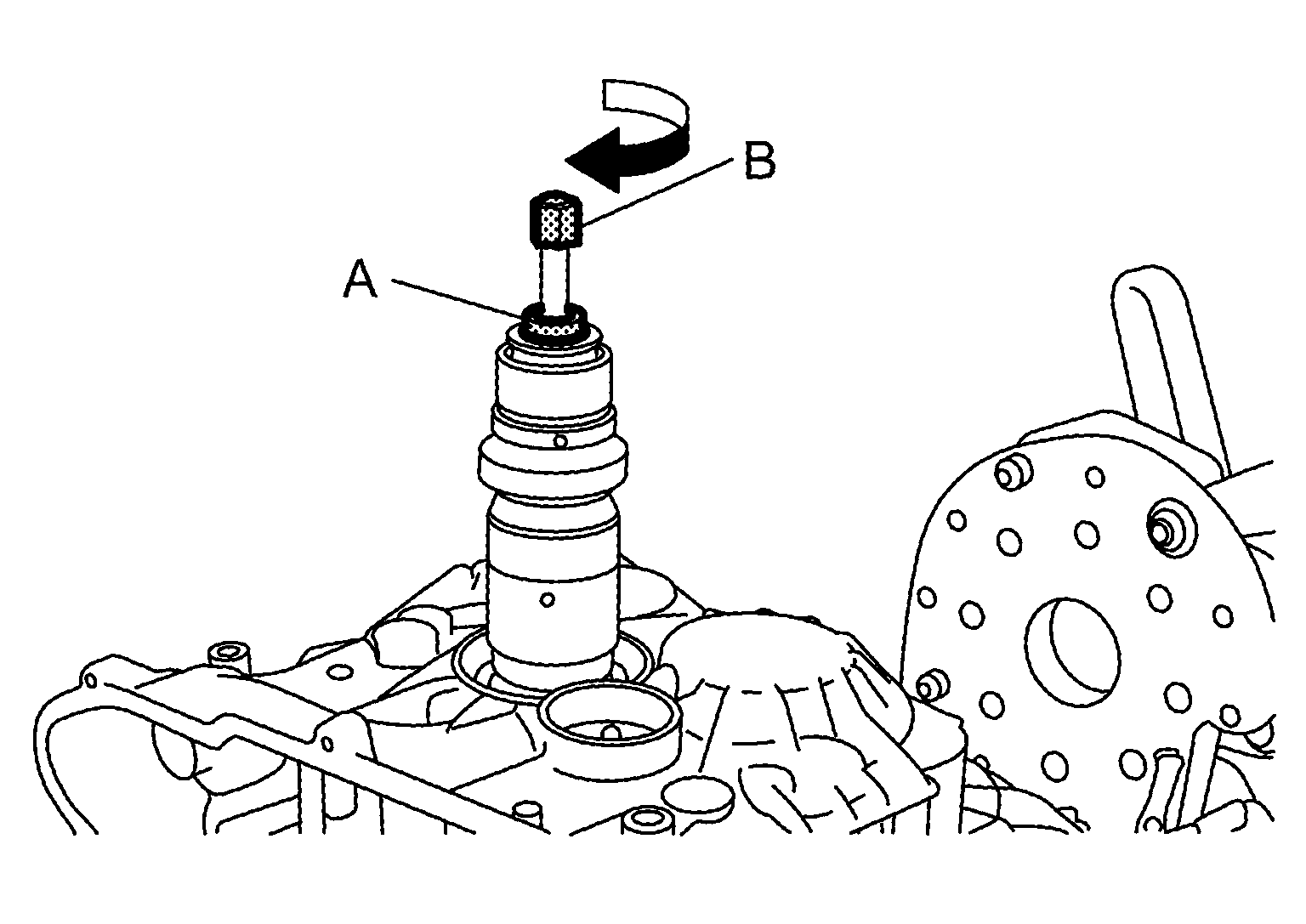
- Remove transaxle case by holding the portion (A) with suitable tool and turn the portion (B) to the direction shown by figure.
 Courtesy of NISSAN NORTH AMERICA, INC. Courtesy of NISSAN NORTH AMERICA, INC.
|
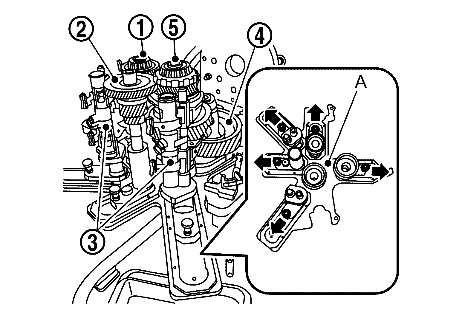
- Remove 3rd, 6th, 7th, and reverse gear output shaft
, input shaft
 , Shift fork
  , final drive
  , 1st, 2nd, 4th, and 5th gear output shaft
  by pulling the lever of assembly device (A) to the directions shown by arrows.
 Courtesy of NISSAN NORTH AMERICA, INC. Courtesy of NISSAN NORTH AMERICA, INC.
|