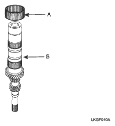
- Install the 3rd needle bearing (A) on the input shaft (B).
 Courtesy of KIA MOTORS AMERICA, INC.
- Apply transaxle oil to the needle bearing.
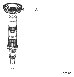
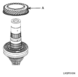
- Install the 3rd gear (A).
 Courtesy of KIA MOTORS AMERICA, INC.
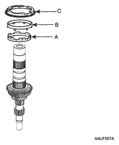
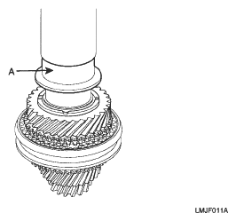
- Install the 3rd inner synchronizer ring (A). (Double cone type)
 Courtesy of KIA MOTORS AMERICA, INC.
- Install the 3rd synchronizer cone (B).
- Install the 3rd outer synchronizer ring (C).
NOTE:
Pay attention the direction of protrusion of a synchronizer ring.
 Courtesy of KIA MOTORS AMERICA, INC.
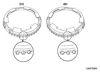
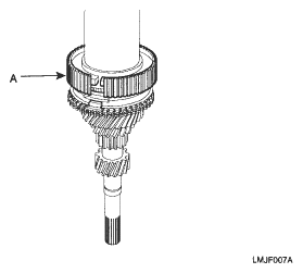
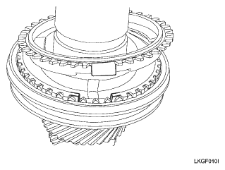
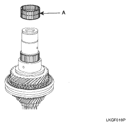
- Assemble the 3rd & 4th synchronizer hub (A) using press.
NOTE:
- When installing the synchronizer hub, make sure that the fingers of synchronizer ring are seated correctly in its groove on the synchronizer hub.
- After installation of the synchronizer hub, check that synchronizer hub rotates smoothly.
 Courtesy of KIA MOTORS AMERICA, INC.
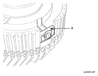
- Install the synchronizer keys (A).
 Courtesy of KIA MOTORS AMERICA, INC.
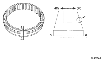
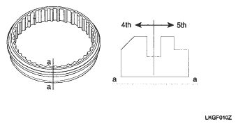
- Install the 3rd & 4th synchronizer sleeve.
NOTE:
- Put down the 3rd slope face of sleeve with the identification mark.
- Make sure that the groove of sleeve inside is seated correctly in the groove of synchronizer hub.
 Courtesy of KIA MOTORS AMERICA, INC.
 Courtesy of KIA MOTORS AMERICA, INC.
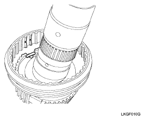
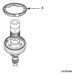
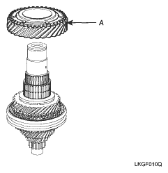
- Install the 4th outer synchronizer ring (A).
NOTE:
When installing the synchronizer ring, make sure that the fingers of synchronizer ring are seated correctly in the grooves of the 3rd & 4th synchronizer hub.
 Courtesy of KIA MOTORS AMERICA, INC.
 Courtesy of KIA MOTORS AMERICA, INC.
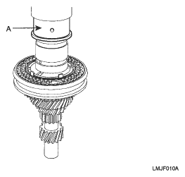
- Install the 4th gear sleeve (A) using press.
 Courtesy of KIA MOTORS AMERICA, INC.
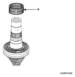
- Install the 4th needle bearing (A).
 Courtesy of KIA MOTORS AMERICA, INC.
- Apply transaxle oil to the needle bearing.
- Install the 4th gear (A).
 Courtesy of KIA MOTORS AMERICA, INC.
- Install the 5th sleeve (A) using press.
 Courtesy of KIA MOTORS AMERICA, INC.
- Install the 5th needle bearing (A).
 Courtesy of KIA MOTORS AMERICA, INC.
- Install the 5th gear (A).
 Courtesy of KIA MOTORS AMERICA, INC.
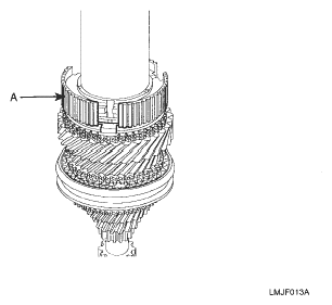
- Install the 5th synchronizer ring (A).
 Courtesy of KIA MOTORS AMERICA, INC.
- Install the 5th synchronizer hub (A) using the press.
NOTE:
- When installing hub, make sure the direction as shown in the picture.
- When pressing the hub, make sure that the fingers of the 5th synchronizer ring (double cone) are seated correctly in the grooves of the hub.
 Courtesy of KIA MOTORS AMERICA, INC.
 Courtesy of KIA MOTORS AMERICA, INC.
- Install the synchronizer key (A).
Courtesy of KIA MOTORS AMERICA, INC.
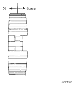
- Install the 5th synchronizer sleeve.
NOTE:
- Put down the 5th slope face of sleeve with the identification mark.
- Make sure that the groove of sleeve inside is seated correctly in the groove of synchronizer hub.
Courtesy of KIA MOTORS AMERICA, INC.
 Courtesy of KIA MOTORS AMERICA, INC.
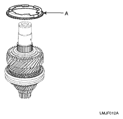
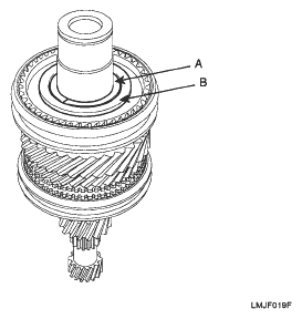
- Install the spacer (A) and ring (B).
 Courtesy of KIA MOTORS AMERICA, INC.
- Install the spacer (A).
 Courtesy of KIA MOTORS AMERICA, INC.
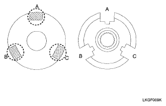
NOTE:
When installing the spacer, make sure that three fingers of spacer are seated correctly in three grooves of 5th synchronizer hub.
 Courtesy of KIA MOTORS AMERICA, INC.
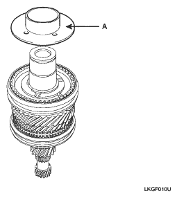
- Install the thrust washer.
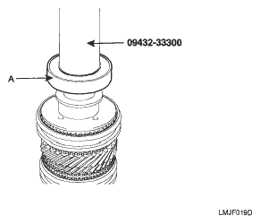
- Install the ball bearing (A) by press and special tool (09432-33300).
 Courtesy of KIA MOTORS AMERICA, INC.
- Install the snap ring.
- Install the front input shaft ball bearing by press and special tool (09432-33300).
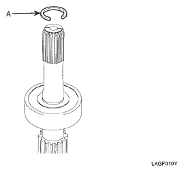
- Install the snap ring (A).
 Courtesy of KIA MOTORS AMERICA, INC.