DTC C0200/31 Front Speed Sensor RH Circuit; DTC C0205/32 Front Speed Sensor LH Circuit; DTC C1271/71 Low Output Signal of Front Speed Sensor RH (Test Mode DTC); DTC C1272/72 Low Output Signal of Front Speed Sensor LH (Test Mode DTC): Description
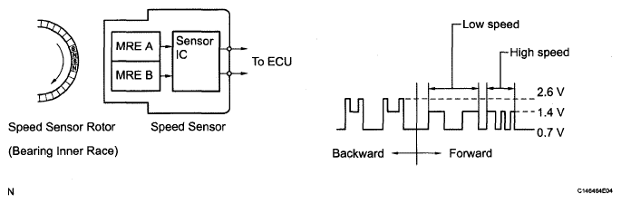
The speed sensor detects the wheel speed and sends the appropriate signals to the skid control ECU. These signals are used for the ABS control system. This speed sensor contains a sensor IC, which consists of 2 MREs (Magnetic Resistance Elements). The speed sensor rotor, which consists of 48 sets of N and S poles arranged in a circle, is integrated with the inner race of the hub bearing.
To detect the direction, the output waves are used to determine the relationship of the pulses that are generated by the 2 MREs. Upon receiving this signal, the sensor IC outputs a forward or backward waveform to the ECU.
DTCs C1271/71 and C1272/72 will be deleted when the speed sensor sends a vehicle speed signal or when Test Mode ends. DTCs C1271/71 and C1272/72 are output only in Test Mode.
 Courtesy of © TOYOTA, LICENSE AGREEMENT TMS1002
 DTC CODE REFERENCE CHART
| DTC Code |
DTC Detection Condition |
Trouble Area |
C0200/31
C0205/32 |
Any of the following is detected:
- At a vehicle speed of 10 km/h (6 mph) or more, an open or short in the sensor signal circuit continues for 1 second or more.
- Momentary interruption of the sensor signal from the abnormal wheel occurs 255 times or more.
- An open in the speed sensor signal circuit continues for 0.5 seconds or more.
- When the vehicle is driven in reverse at the speed of 3 km/h (1.8 mph) or more and 3 of the wheel sensors detect the reverse signal, the other sensor detects a high frequency pulse 75 times.
- At a vehicle speed of 10 km/h (6 mph) or more, the vehicle speed sensor output drops by 50% for 5 seconds.
- At a vehicle speed of 10 km/h (6 mph) or more, the direction of wheel rotation changes 7 times in 0.006 seconds.
- At a vehicle speed of 30 km/h (18 mph) or more, one wheel direction is different from the other 3 wheels for 1 second.
- At a vehicle speed of 100 km/h (60 mph), a reverse signal is output for 1 second or more.
- At a vehicle speed of 30 km/h (18 mph) or more, the rotation direction of the one of the wheels is not detected normally and the rotation direction of the other 3 wheels is not the same for 1 second.
- With the IG1 terminal voltage 9.5 V or more, the sensor power supply voltage decreases for 0.5 seconds or more.
|
- Front speed sensor RH/LH
- Speed sensor circuit
- Speed sensor rotor
- Sensor installation
- Skid control ECU
|
C1271/71
C1272/72 |
Detected only during Test Mode. |
- Front speed sensor RH/LH
- Sensor installation
- Speed sensor rotor
|
HINT:
- DTCs C0200/31 and C1271/71 are for the front speed sensor RH.
- DTCs C0205/32 and C1272/72 are for the front speed sensor LH.