October 30: LEMON manuals on a temporary server, it is slow and having issues, download the manuals you need! Later in November we will switch back to the fast server.
Powertrain Control Module (Pcm) Malfunction
NOTE:
The following test procedures are for DTCs P0603, P0605, P0606, P1633 and P1639.
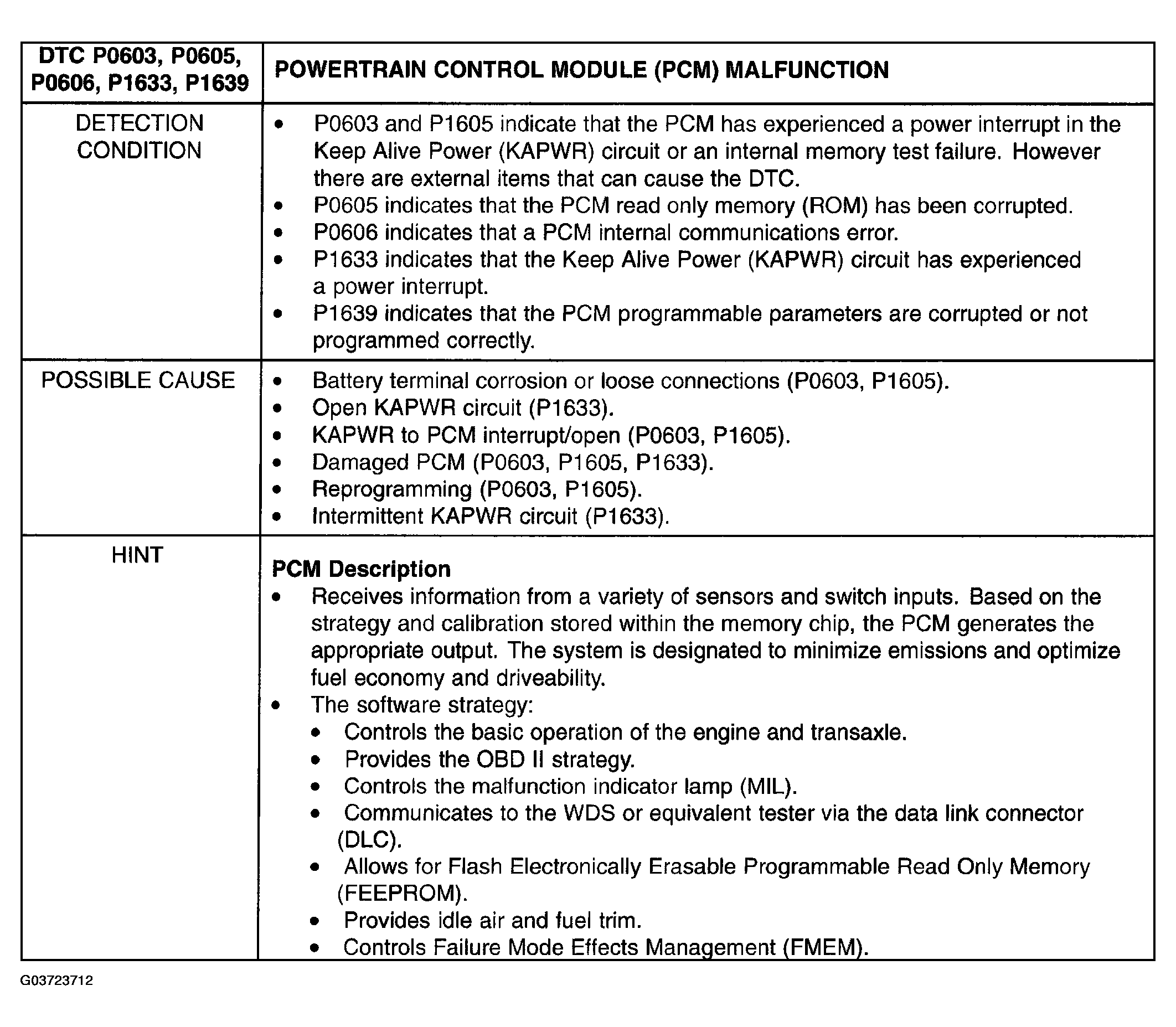 Courtesy of MAZDA MOTORS CORP.
POWERTRAIN CONTROL MODULE (PCM) MALFUNCTION INSPECTION/ACTION CHART
| STEP |
INSPECTION |
ACTION |
| 1 |
- Was PCM Quick Test performed?
|
Yes |
For DTC P0605 or P1639, go to next step.
For all others, go to step 3. |
| No |
Perform PCM Quick Test. See
PCM QUICK TEST
. |
| 2 |
PROGRAM PCM PARAMETERS
- Connect WDS or equivalent tester with flash cable.
- Key ON, Engine OFF (KOEO).
- Select Diagnostic Data Link.
- Select PCM.
- Select Module Configuration and follow directions to access.
- Scroll to tire size and press Trigger.
- Turn dial to select 720 for 235/70R16 tires or 749 for 215/70R16 tires then press Trigger.
- Scroll to axle ratio and press Trigger.
- Turn dial to select 3.78 and press Trigger.
- Press Start to program PCM parameters.
- Press Cancel to return to the first screen.
- Was programming successful?
|
Yes |
Clear DTCs and perform a brief drive cycle (of at least 1/4 mile). Start and stop the vehicle two times during the drive, cycling the key off and on.
Go to step 6. |
| No |
See
DIAGNOSTIC INDEX
. |
| 3 |
CHECK BATTERY TERMINALS
NOTE:
- If KAPWR is interrupted to the PCM (that is, when a Breakout Box is installed or the battery is disconnected), DTCs P0603/P1605 can be generated on the first power-up.
- Inspect the battery cables for loose connections, corrosion.
- Are the battery terminal connections in good condition?
|
Yes |
Go to next step. |
| No |
Repair battery terminals as necessary.
Go to step 6. |
| 4 |
INSPECT ENGINE COMPARTMENT FOR PROPER WIRE ROUTING
- Inspect engine compartment wiring for proximity to ignition components or wires.
- Is wiring too close to ignition components or wires?
|
Yes |
Reroute wires as necessary.
Go to step 6. |
| No |
Engine compartment wire routing is OK.
Go to next step. |
| 5 |
CHECK KEEP ALIVE POWER (KAPWR) TO PCM
- Disconnect PCM.
- Install Breakout Box, leave PCM disconnected.
- Measure voltage between test pin C45 (KAPWR) and test pin C49 (PWR GND).
- While observing multimeter, grasp the engine harness and wiggle, shake or bend a small section while working from the PCM to the dash panel.
- Does the voltage reading indicate less than 10.5 V?
|
Yes |
Isolate and repair open in KAPWR circuit.
Go to next step. |
| No |
No open in KAPWR harness circuit detected.
Go to next step. |
| 6 |
VERIFY TROUBLESHOOTING OF DTCs COMPLETED
- Make sure to reconnect all disconnected connectors.
- Clear DTCs from PCM memory using WDS or equivalent tester generic OBD II function.
- Perform PCM Quick Test. See
PCM QUICK TEST
.
- Is same DTC present?
|
Yes |
Replace PCM.
See
POWERTRAIN CONTROL MODULE (PCM)
.
Repeat PCM Quick Test. See
PCM QUICK TEST
. |
| No |
If any other DTC is present, go to applicable DTC inspection.
If no DTC is present, troubleshooting complete. |