Relay And Fuse Block Removal/Installation: Installation
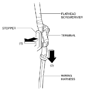
- While pressing the stopper using a tape-wrapped flathead screwdriver in the direction of the arrow (1) shown in the figure, pull the wiring harness in the direction of the arrow (2) shown in the figure to detach the fuse terminal from the stopper.
 Courtesy of MAZDA MOTORS CORP.
CAUTION:
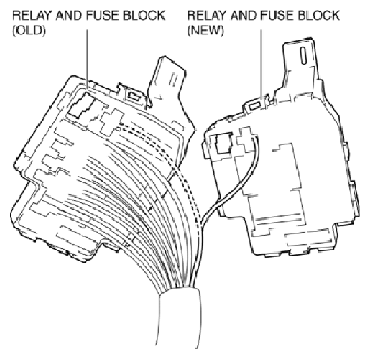
- If terminals are installed incorrectly, it could damage electrical accessories and burn wiring harnesses. When relocating terminals after replacing the relay and fuse block, line up the relay and fuse blocks of old and new parts and always verify each of the wiring harnesses in the wiring diagram so that the installation positions are correct.
- A terminal disconnection could cause electronic components and the system to not operate normally due to poor contact. After terminal relocation, lightly pull the wiring harnesses to verify that they cannot be pulled out.
- Relocate all relay and fuse terminals to the new relay and fuse block.
 Courtesy of MAZDA MOTORS CORP.
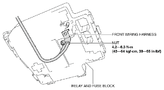
- Install the front wiring harness.
 Courtesy of MAZDA MOTORS CORP.
- Install the nut.
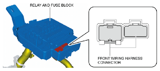
- Insert the front wiring harness connectors into the relay and fuse block.
 Courtesy of MAZDA MOTORS CORP.
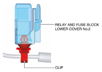
- Install the wiring harness clip to the relay and fuse block lower cover No. 2.
 Courtesy of MAZDA MOTORS CORP.
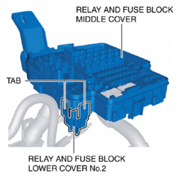
- Insert all of the relay and fuse block middle cover tabs into the relay and fuse block lower cover No. 2.
 Courtesy of MAZDA MOTORS CORP.
- Install the relay and fuse block lower cover No. 2 to the relay and fuse block middle cover.
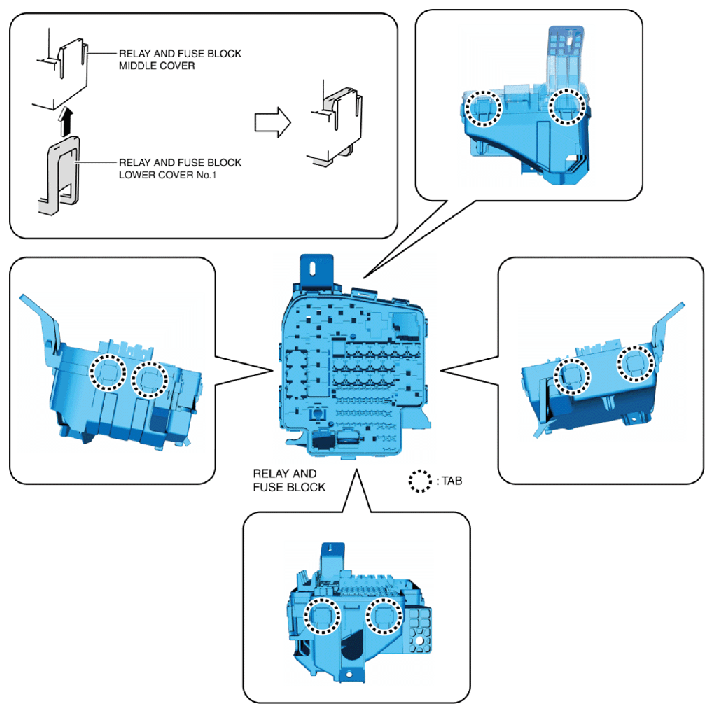
- Insert all of the relay and fuse block middle cover tabs into the relay and fuse block lower cover No. 1.
 Courtesy of MAZDA MOTORS CORP.
- Install the relay and fuse block lower cover No. 1 to the relay and fuse block middle cover.
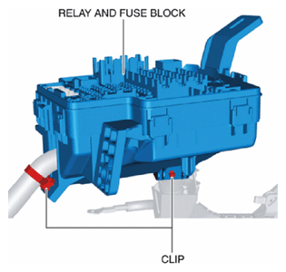
- Install the wiring harness clips.
 Courtesy of MAZDA MOTORS CORP.
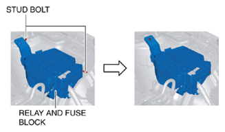
- Insert the relay and fuse block into the stud bolts.
 Courtesy of MAZDA MOTORS CORP.
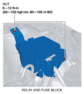
- Install the nuts.
 Courtesy of MAZDA MOTORS CORP.
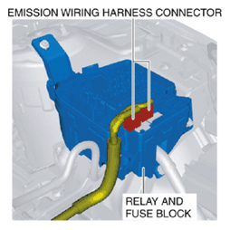
- Connect the emission wiring harness connectors.
 Courtesy of MAZDA MOTORS CORP.
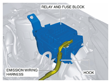
- Press the emission wiring harness into the relay and fuse block hook.
 Courtesy of MAZDA MOTORS CORP.
- Install all the relays and fuses.
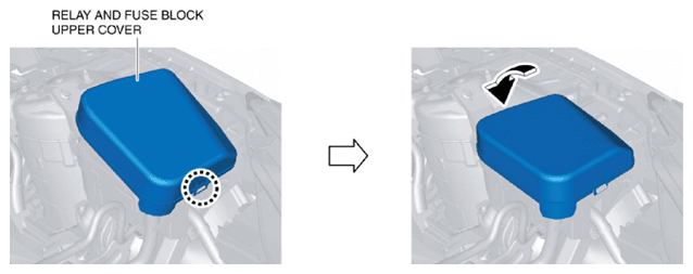
- Install the relay and fuse block upper cover.
 Courtesy of MAZDA MOTORS CORP.
- Install the battery and the battery tray. (See BATTERY REMOVAL/INSTALLATION [SKYACTIV-G 2.0]
.)
- Install the air cleaner assembly. (See INTAKE-AIR SYSTEM REMOVAL/INSTALLATION [SKYACTIV-G 2.0]
.)
- Perform the "Verify Relay and Fuse Block Replacement ". (See Verify relay and fuse block replacement .)