MPI Control Relay
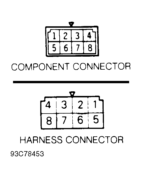
- This step checks ignition switch supply voltage of control relay. Disconnect control relay connector. Turn ignition on. Using DVOM, measure voltage between terminal No. 8 of relay harness connector and vehicle ground. See Fig 1
. If voltage is battery voltage, go to step 2. If voltage is not battery voltage, check and repair circuit between ignition switch and control relay.
- This step checks continuity of control relay ground circuit. Turn ignition off. Using DVOM, check continuity between control relay harness connector terminal No. 6 and vehicle ground. If continuity exists, go to step 3. If continuity does not exist, check and repair circuit between control relay and vehicle ground.
- This step checks battery supply voltage of control relay. Using DVOM, measure voltage between terminal No. 4 of relay harness connector and vehicle ground. If voltage is battery voltage, go to step 4. If voltage is not battery voltage, check and repair circuit between battery and control relay.
- This step checks continuity of circuit between control relay and ECM. Disconnect ECM connector. Using DVOM, check continuity between control relay harness connector terminal No. 3 and ECM connector terminals No. 12 and 25. See Figure
and Fig 1
. If continuity exists, go to step 5. If continuity does not exist, check and repair circuits between control relay harness connector and ECM.
- This step checks supply voltage to control relay actuator. Connect ECM and MPI control relay connectors. Using DVOM, backprobe control relay terminal No. 2. With engine cranking, voltage should be 8 volts or greater. Start engine and run at 2500 RPM or greater. If voltage is battery voltage, harness is okay. If voltage is not battery voltage, go to step 6.
- If control relay tests okay in steps 6 through 8, replace ECM. Removal of relay may assist in testing. Continuity should exist between terminals No. 5 and 7. Measure resistance between terminals No. 6 and 8. Continuity should exist in only one direction. Replace control relay if continuity is not as specified.
- Connect 12-volt power source between relay terminals No. 5 and 7. Connect positive lead to terminal No. 7. With relay energized, battery voltage should exist between terminals No. 1 and 5. With power source removed, voltage should not exist.
- Move 12-volt power source to relay terminals No. 6 and 8. Connect positive lead to terminal No. 8. With relay energized, continuity should exist between terminals No. 2 and 4 and between terminals No. 3and 4. With power source removed, continuity should not exist. Replace control relay if measurements are not as specified.
 Courtesy of MITSUBISHI MOTOR SALES OF AMERICA.