Scan Tester Procedure
Access scan tester service data item No. 11. Tester should display sensor voltage. Ensure engine is at normal operating temperature. See HO2S OPERATING VOLTAGE SPECIFICATIONS
table.
HO2S OPERATING VOLTAGE SPECIFICATIONS
| Engine RPM |
Output (Volts) |
| 750 |
.4 Or Less |
| 2000 |
.6-1.0 |
| 4000 To 750 |
.2 Or Less |
| 750 To 4000 |
.6-1.0 |
- Measure power supply voltage. Disconnect both HO2S harness connectors. Turn ignition on. Using DVOM, measure voltage between harness connector terminal No. 4 of front sensor and ground, and terminal No. 3 of rear sensor and ground. See Figure
. If voltage measured is less than battery voltage, inspect and repair circuit from MFI relay to HO2S sensors as needed.
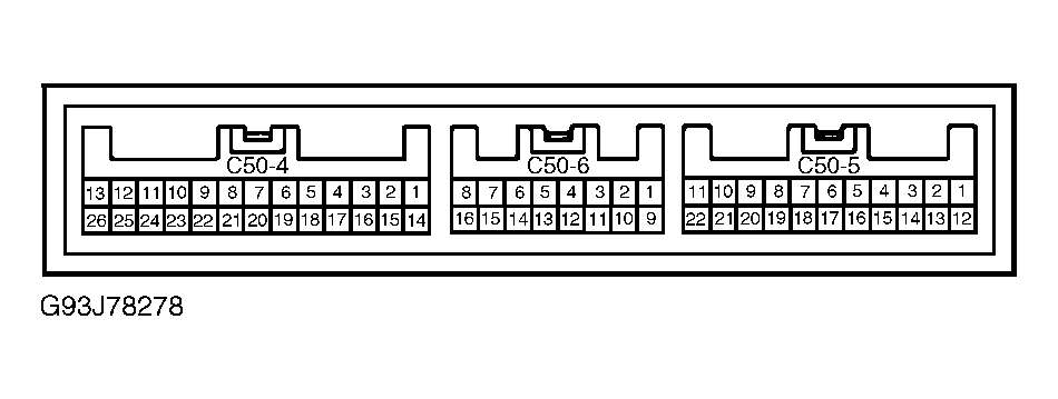
- Check continuity of ground circuit to ECM. Turn ignition off. Disconnect ECM harness connector. For front sensor, connect jumper wire between ECM harness connector terminal No. 6, connector No. C50-5 and vehicle ground. See Fig 1
. Check resistance between front sensor harness connector terminal No. 1 and vehicle ground. If continuity does not exist, inspect and repair circuit as needed.
- Move jumper wire to ECM harness connector terminal No. 7, connector No. C50-5. See Fig 1
. Check resistance between rear sensor harness connector terminal No. 1 and vehicle ground. If continuity does not exist, inspect and repair circuit as needed.
- Check continuity of sensor ground circuits. Using ohmmeter, check resistance between harness connector terminals No. 2 and 3 of front sensor and ground, and terminals No. 2 and 4 of rear sensor and ground. If continuity does not exist, inspect and repair circuits as needed.
 Courtesy of HYUNDAI MOTOR CO.